
Cambridge - Its Railways and Station
[Source:
Darren Kitson]
Part 3: The Big Four Period
As we saw in Part 2, on and from 1 January 1923 the GER and GNR became part of the London & North Eastern Railway (LNER) and the MR and LNWR became part of the London, Midland & Scottish Railway (LMS). Cambridge thus was served by just two companies instead of the previous four; the LMS via Bedford and from Kettering with all other services being LNER. The LNER and LMS together with the Southern Railway and Great Western Railway formed what was coined 'The Big Four'. Part 3 covers this period, but with the Second World War and the period to Nationalisation covered separately in Part 4.
Thoughts of the LNER instantly conjure up images of H. N. Gresley, better known as Nigel Gresley, his Pacific locomotives and bow-ended teak carriages. Gresley had begun his railway career in the north of England and in 1905 became Carriage & Wagon Superintendent of the GNR until he succeeded Henry A. Ivatt (not to be confused with Henry G. Ivatt of the LMS) as Chief Mechanical Engineer (CME) of the same company in 1911. He then held the same position within the LNER following the latter's formation.
 Gresley's influence was therefore felt at Cambridge long before the LNER came into existence with his articulated twin sets, K3 and N2 locomotives among others. He was later to leave his mark on Cambridge in a bigger way with his B17 locomotives, also known as the 'Sandringham' or 'Footballer' Class. Sir Nigel Gresley became so-titled in 1936, having been knighted by King Edward VIII who was to abdicate later that same year. He died on 5 April 1941 at Watton-at-Stone, Hertfordshire, aged 64 years. Gresley was succeeded by Edward Thompson as CME until 1946 when Arthur Peppercorn took over until nationalisation. Gresley's influence was therefore felt at Cambridge long before the LNER came into existence with his articulated twin sets, K3 and N2 locomotives among others. He was later to leave his mark on Cambridge in a bigger way with his B17 locomotives, also known as the 'Sandringham' or 'Footballer' Class. Sir Nigel Gresley became so-titled in 1936, having been knighted by King Edward VIII who was to abdicate later that same year. He died on 5 April 1941 at Watton-at-Stone, Hertfordshire, aged 64 years. Gresley was succeeded by Edward Thompson as CME until 1946 when Arthur Peppercorn took over until nationalisation.
The situation in respect of the LMS at Cambridge was such that former LNWR locomotives continued to appear; 'Precursor; (4-4-0 version); 'George the Fifth'; 'Claughton' types as well as the so-called 'Cauliflower' 0-6-0 and the 'Webb' 2-4-2 tanks among others on the line from Bedford. On the former Midland line, the same small and increasingly antiquated 'Kirtley' and 'Johnson' locomotives continued to appear due to the weak bridges along the line.
The LMS had rather more CMEs than the LNER; George Hughes; Henry Fowler; Ernest Lemon; William Stanier; Charles Fairburn; Henry G. Ivatt. Of those, the tenure of Ernest Lemon was the shortest (1931 - 1932) while that of William Stanier, later Sir, was the longest (1932 - 1944). Charles Fairburn also served for only one year, 1944 - 1945. Of those, Ernest Lemon was a rather surprising choice for CME as he was a carriage and wagon man with little experience of locomotives. As a result, Lemon was to be the only LMS CME who did not design his own locomotives. Fairburn, despite also only serving as CME for one year, left rather more of a mark. He had been Stanier's deputy and took over upon retirement of the latter. Fairburn produced his 2-6-4T locomotives, actually a rework of a Stanier design, was behind the introduction of diesel shunters to the LMS and sowed the seeds for the LMS diesel locomotives 10000/1 which appeared under the auspices of H. G. Ivatt. The LMS diesel shunters culminated in the LMS/BR Class 11 and then the BR Class 08/09/10. Examples of Classes 08/10/11 were allocated to Cambridge at various times. Insofar as steam locomotives and rolling stock was concerned, with the obvious exception of Lemon, examples of the work of all LNER and LMS CME's could be seen at Cambridge. Even examples of the ugly Hughes 'Crab' 2-6-0 put in appearances from time to time while larger locomotives of the LNER, normally associated with the East Coast Main Line, including the A4s, were often seen.
The LNER 1926 Resignalling
This was the first event of any note to occur under LNER auspices and it involved the resiting and rebuilding of Cambridge North and South signal boxes plus the abolition of Central, Hills Road and Mill Road boxes. All were demolished with the exception of Mill Road which, as we have already seen, survived for a further half-century as a store. It is possible Mill Road also served, for a time, reduced in status to a shunting frame for the private sidings which once existed on the down side and north of Mill Road bridge. Two of these sidings were Cambridge Corporation and the Co-op with the former existing until the mid 1980s albeit long since disused.
The resignalling was part of a broader scheme between Cambridge and March but that within the Cambridge station area was unique. It was all-electric, rather than electro-pneumatic as installed in other areas, and the equipment was supplied by the British Power Railway Signal Co. (BPRS). As far as signalling was concerned, this firm was somewhat in competition with Westinghouse but nevertheless supplied equipment to railways in many parts of the world, most notably Argentina.
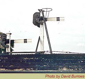
 BPRS supplied Cambridge with lower quadrant signals using tapered arms, in metal, with strengthening corrogations rather than flanges as found on other signal arms. These BRPS arms were said to be of a design originally produced for Australia. Electrically operated ground signals (shunt signals) were also provided and certain of these were fitted with semaphore arms, as opposed to discs, made from vulcanised rubber to minimise the possibility of damage resulting from clearance issues. It was these two features which made this signalling unique to Cambridge. BPRS supplied Cambridge with lower quadrant signals using tapered arms, in metal, with strengthening corrogations rather than flanges as found on other signal arms. These BRPS arms were said to be of a design originally produced for Australia. Electrically operated ground signals (shunt signals) were also provided and certain of these were fitted with semaphore arms, as opposed to discs, made from vulcanised rubber to minimise the possibility of damage resulting from clearance issues. It was these two features which made this signalling unique to Cambridge.
The 1926 North and South boxes were fitted with miniature levers and illuminated diagrams as was normal with non-mechanical signalling, while certain signals were fitted with theatre indicators to inform drivers which road their trains were to take and which platforms their trains were to enter as appropriate.
Points were also fitted with electric motors. In operation, the BPRS point motors could be heard to start and run for a second or two before the point blades moved; indicating that either a centrifugal clutch or bendix was used - it is not clear which. Point locking was achieved automatically within the motor and gearbox assembly. Signal motors were mounted towards the bottom of signal posts and there was, of course, a motor for each signal arm. Theatre Indicators displayed either a letter or a number as appropriate and operation was automatic according to how points and signals were set but indications could be over-ridden by the signalmen under certain circumstances.
The equipment gave good service for half a century but by the 1970s maintenance began to become a liability and increasingly stringent regulations did not help.
The lower quadrant signals began to be replaced by upper quadrant types and the BPRS system was finally swept away during the 1970s resignalling carried out as a prelude to electrification. During this period, Cambridge had an odd mix of upper and lower quadrant and colour-light signals. Modernisation was finally accomplished with the opening of Cambridge Power Signal Box in 1981, which had been in planning since 1975, and at the time of writing even this is due to be made redundant with control transferring to Romford.
 Cambridge also had certain sets of points equipped with gas heating, to prevent the moving components freezing during periods of low temperatures. These consisted of tubes a few feet long with burner jets at intervals along their lengths, the flames being directed onto the outer faces of the rails. Cambridge also had certain sets of points equipped with gas heating, to prevent the moving components freezing during periods of low temperatures. These consisted of tubes a few feet long with burner jets at intervals along their lengths, the flames being directed onto the outer faces of the rails.
Right two of the 1926 BPRS lower quadrant signals can be seen. This particular pair were located on Mill Road bridge and controlled trains in the up direction. There were theatre indicators for platforms 1, 4 ,5 or 6, for the through road or the various carriage and locomotive sidings. up trains for the goods yard or the goods lines avoiding the station had been signalled and switched prior to reaching this point.
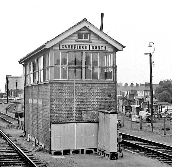
Photo by Alan Brown
For reasons of image availability we need once again to use some images from the BR period. Above is the 1926 Cambridge North box, located just south of Mill Road bridge and on the down side. It replaced the original North box which, as we have seen, was sited at the end of platforms 4 and 5. The track on the left is the down main while that to the right leads to the locomotive stabling sidings on the site of the former steam shed approach roads. The siding ending at the buffer stop was often used, in BR days, for stabling diesel multiple units during turns.
Behind the box on the right was some sort of small pit, perhaps an inspection chamber for drains. For many years during the 1970s this pit was covered by half of a running-in board from Bartlow station, which had closed in March 1967.
The timber yard on the right was once the Midland Railway's goods (probably coal) yard. An LMS record from 1943 reveals this yard, known as Mill Road Depot, was under that company's ownership but with Messrs Travis & Arnold, timber merchants, as tenants. Its last railway use was as a PW engineers depot and an LNER Sentinel shunter could often be seen there. Later, Barclay diesel shunter Departmental No. 81 was reportedly also seen there, although this locomotive seems to have spent much of its time at Peterborough. It later became D2956 when the original locomotive bearing that number was withdrawn. The latter has survived into preservation whereas the former was scrapped.
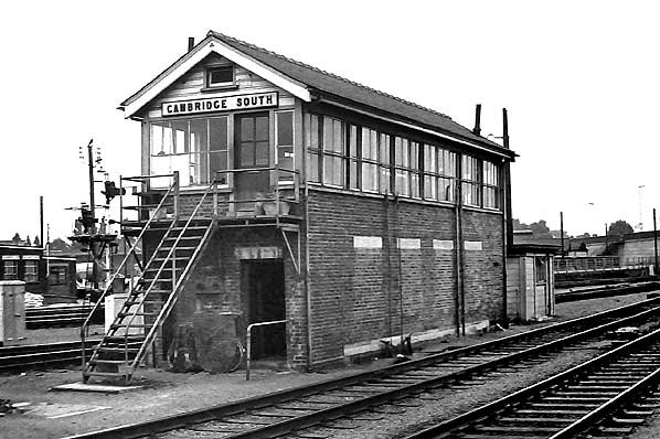 Photo by Alan Brown Photo by Alan Brown
Above is the 1926 South box, rather larger than North box and it was the busier of the two. Like North, it had replaced an original box which had stood at the end pf the platform - in this case platforms 1 and 2. The tracks to the left of the box ran into the carriage sidings while beyond those were the through goods roads. At one time there was a constant procession of goods trains using the latter roads, as well as diverted East Coast trains and Newmarket race specials.
 Royal trains, a common sight at Cambridge, did not lower the tone by using the goods roads but instead always passed through Cambridge via the platform roads. Members of the Royal Family often visit Cambridge by train and have done so since 1847, usually in connection with the university, as well as passing through en route to Sandringham following Queen Victoria's purchase of Sandringham House in 1862. Today, with these journeys being only short runs from London, especially if only travelling to Cambridge, the royal train is seldom used and it is common for The Queen and other members of the Royal Family to travel by timetabled service train; an ordinary outer-suburban electric multiple unit. This is normally from King's Cross as this avoids the formalities needed for the Monarch to enter the City of London in which Liverpool Street station is located. Also, the vast majority of trains to King's Lynn (now the nearest station to Sandringham) nowadays run to and from King's Cross. Royal trains, a common sight at Cambridge, did not lower the tone by using the goods roads but instead always passed through Cambridge via the platform roads. Members of the Royal Family often visit Cambridge by train and have done so since 1847, usually in connection with the university, as well as passing through en route to Sandringham following Queen Victoria's purchase of Sandringham House in 1862. Today, with these journeys being only short runs from London, especially if only travelling to Cambridge, the royal train is seldom used and it is common for The Queen and other members of the Royal Family to travel by timetabled service train; an ordinary outer-suburban electric multiple unit. This is normally from King's Cross as this avoids the formalities needed for the Monarch to enter the City of London in which Liverpool Street station is located. Also, the vast majority of trains to King's Lynn (now the nearest station to Sandringham) nowadays run to and from King's Cross.
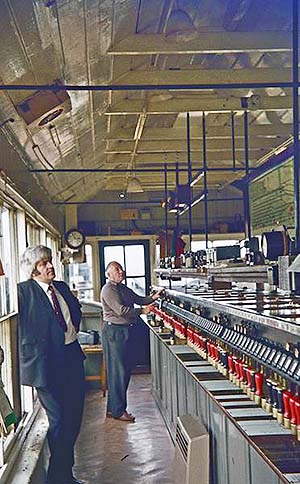
Above the interior of Cambridge South box (Photo by Geoff Skelsey) can be seen in September 1974. Note the small levers; all that is required for electric operation. The block instruments are located above the banks of levers with the track and signalling diagram presiding over the whole. Cambridge North box was smaller but otherwise to the same design.
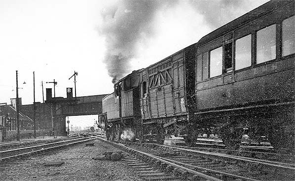
Photo by John Ford from David Ford's Flickr photostream
Above we can see an LMS train departing from Cambridge with a Stanier 2-6-4T in charge around the end of the LMS's existence. The bracket signal is one of those installed in 1926 and the image offers a rare glimpse of a theatre indicator in operation. The indication B is for Branch, meaning the train will branch off onto the Bedford line. Other indications, at these signals, were M for Main line (London via either route or the Stour Valley line), R for Relief (trains being switched onto the up relief line). There may have been other indications too. The shorter signal controlled the exit from the up goods yard. The signal stands on the site of the former Hills Road Junction box. The junction ahead of the locomotive continued to be referred to as Hills Road Junction while immediately beyond the bridge was Cambridge (LNW) Junction.
 The signals seen above were familiar to generations of railway fans who would congregate by the railings on the left. Some appear to be present in the image. Note the steps leading down from Hills Road; these disappeared when the bridge was rebuilt c1960 leaving anybody who wanted access to the railings or the road behind them, which went to the goods sheds, to make a detour via the Hills Road / Cherry Hinton Road junction at the foot of the bridge. The signals seen above were familiar to generations of railway fans who would congregate by the railings on the left. Some appear to be present in the image. Note the steps leading down from Hills Road; these disappeared when the bridge was rebuilt c1960 leaving anybody who wanted access to the railings or the road behind them, which went to the goods sheds, to make a detour via the Hills Road / Cherry Hinton Road junction at the foot of the bridge.
Just beyond the bridge on the left another signal post can be seen; this was a shunt signal and also had a theatre indicator but its purpose (the theatre) is something of a mystery. There were other theatre indicators south of Hills Road bridge, on the lines from London and from Bedford.
Note the electric point motors and the horsebox. Horse boxes were once a familiar sight all over Britain's railway network and that included the Metropolitan Railway. As above, horse boxes were usually, if not always, XP rated, meaning they could run in express passenger trains. They were not classed as goods vehicles but as non passenger carrying coaching stock (NPCS) and could also form a complete train if required, the latter once being a common sight heading to and from Newmarket. We should remember that at one time horses did not just appear at the races; the railways used them for shunting; farmers used them; road hauliers used them for local delivery rounds so the transport of horses was once big business for the railways.
The horsebox in the above image appears to be an ex North British Railway Diagram 110 example dating from the early 1900s. It was by no means unusual to see horse boxes a long way from their native haunts. The panel in the side of the horsebox hinged down to form a loading ramp and the two doors above it, with external framing, hinged open as per stable doors. The compartment nearest the camera would store fodder for the horse(s) and there was a toilet for the groom, while that farthest from the camera was for the groom to travel in; horses never travelled alone, a groom was always present. The groom compartment was in effect half a normal passenger compartment with a seat which could in many cases be converted into a bed. An internal corridor connected the two compartments. There were also similar vehicles for the conveyance of pedigree cattle and these could often be distinguished from horse boxes by having only one compartment. Two further images are worth showing here from early BR days:
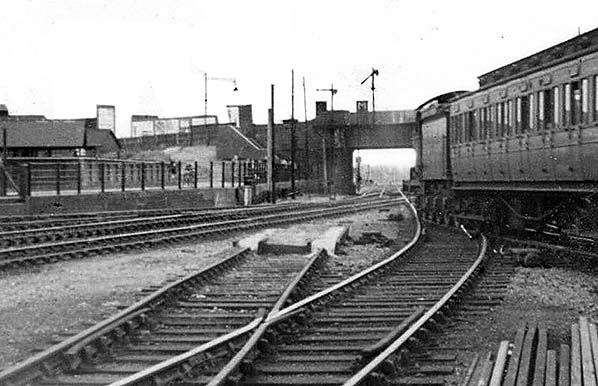
Photo by John Ford from David Ford's Flickr photostream
Above a D16 is seen leaving Cambridge with the theatre indicator showing M for Main line. The train is either a Liverpool Street or Stratford stopper or a Stour Valley line service. The year is 1948 and the locomotive has British Railways in full on its tender. This was a temporary expedient until the appearance of the British Transport Commission 'emaciated ferret' logo aka 'Lion & Wheel'. A clearer view is afforded of the steps down from the road in this image. Clerestory roofed carriages were still quite common at this time, but the survivors were soon ousted by the introduction of BR Mk1 stock in 1951 and the continued building of some pre-nationalisation designs by BR. By 1955 no clerestory stock remained in BR passenger service, although it was still to be seen for many years in departmental use, as camping coaches or simply dumped in sidings. It later reappeared, in 1967, in the form of the ex LT Standard Tube Stock purchased for use on the Isle of Wight.
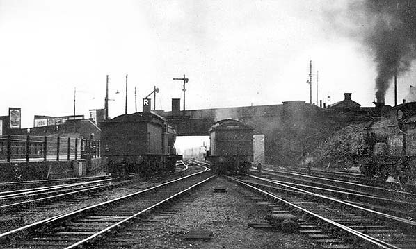
Photo by John Ford from David Ford's Flickr photostream
The above view dates from 1949 and shows the R indication for the locomotive leaving the up goods yard. The locomotives are, from left to right, classes J20, D16 and E4. On the right, behind the bridge, part of the roof of the former LNWR engine shed can be seen. Today the majority of trains passing beneath Hills Road bridge are electric multiple units and with the passage of time it is becoming harder to appreciate that scenes such as that above once existed. The guided busway now passes beneath Hills Road on the right and runs through the site of the former LNWR engine shed.
The Sentinel Steam Railcars
Steam railcars are not usually associated with Cambridge but at an unknown date in 1925 No.13E was allocated to Cambridge. It is known to have worked trials on branches in the area but at the time of writing no further details have come to light. 12E had meanwhile been allocated to Norwich and 13E later joined it there, both operating services in the area until 1930 when Clayton railcars replaced them. The Sentinels were later renumbered 43306/7 respectively and survived until 1940. Unlike most of their sisters, it appears these two railcars never bore names.
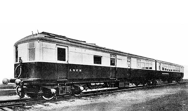
Shortly to follow is the events of the 1930s section but it is convenient to mention here the Sentinel twin-car 'Phenomena'. Numbered 2291 and, oddly considering the railcar was an articulated twin, 2294, 'Phenomena' was a one-off insofar as Britain was concerned as all other Sentinels were single cars.
The Engineer, 28 November 1930
'Phenomena', seen above, had a Woolnough boiler rather than Sentinel's usual vertical boiler as found in their road lorries. There was two engines; one driving the bogie nearest the camera and the second the centre bogie. It is therefore a matter of opinion if this unit was a power-trailer combination or power-twin. In late 1930 or early 1931, the precise date is unclear, 'Phenonema' made a trial run from King's Cross to Cambridge and return. Quite why this route was chosen is not known but such events in the London area were usually for the benefit of the 'brass'; by that time Nigel Gresley was based at King's Cross. Otherwise, 'Phenomena' spent her working life in the north-east and survived until May 1942. Most Sentinels and the similar Clayton railcars were given the quite romantic names formerly applied to stagecoaches. One of the Sentinels, .2136 'Hope', just survived into BR days being withdrawn in February 1948. The majority were withdrawn in the 1943 - 1947 period. The technically correct title for these railcars was Sentinel-Cammell as they were a joint effort between Sentinel and Cammell Laird, or Metro-Cammell after 1929.
 By the time the Sentinel and Clayton cars (of which the latter had a rather disfiguring external coal bunker) appeared, steam railcars had already become something of relics from the past but the Sentinels offered a number of advantages over earlier types and gave the steam railcar a second fling. The Sentinel Waggon Works, Shrewsbury, eventually became part of Rolls-Royce and under that guise produced their well-known range of diesel shunting locomotives which can still be seen pottering around today. By the time the Sentinel and Clayton cars (of which the latter had a rather disfiguring external coal bunker) appeared, steam railcars had already become something of relics from the past but the Sentinels offered a number of advantages over earlier types and gave the steam railcar a second fling. The Sentinel Waggon Works, Shrewsbury, eventually became part of Rolls-Royce and under that guise produced their well-known range of diesel shunting locomotives which can still be seen pottering around today.
Cambridge was, of course, more familiar with Sentinel steam locomotives, with the boxy departmental Class Y1/Y3 shunters of the LNER and the gas works Sentinel which shunted coal wagons at Coldham's Lane until 1969.
Routes and Services
Since the Fordham line opened in 1884, Cambridge had no less than eight routes serving it directly. These were from London (2); Haverhill; Bedford; Newmarket; St Ives; Ely; Fordham/Mildenhall. These routes can be expanded if we include the three converging southwards at Ely, the three* converging at St Ives; the two converging at Newmarket and the two converging at Haverhill.
*Including the lesser known Ely - St Ives line which closed to passengers in 1931 but continued to see excursion trains until 1958.
Of the above routes, a selection of timetabled passenger train services was as follows:
- Liverpool Street - Cambridge and beyond to either Ely / King's Lynn / Hunstanton / Norwich / Yarmouth / Lowestoft / Cromer or York
- St Pancras - Cambridge / Ely / Norwich.
- King's Cross - Cambridge / Ely
- Stratford - Cambridge
- Ipswich / Harwich - Cambridge
- Hunstanton / King's Lynn - Cambridge via Wisbech and March, then via Ely or St Ives
- Peterborough / Ely - Cambridge via Newmarket.
- Mildenhall - Cambridge via Burwell or Newmarket
- Kettering - Cambridge via Huntingdon and St Ives
- Oxford / Bletchley / Bedford - Cambridge
- Clacton / Colchester / Marks Tey - Cambridge via Sudbury or Halstead (The Colne Valley & Halstead Railway remained independent until 1923 when it became part of the LNER. Until then, trains did not under normal circumstances operate to / from Cambridge via Halstead)
- Peterborough East - Ipswich via St Ives with reversal at Cambridge
The summer 1934 working timetable (WTT) for Cambridge, which included both LNER and LMSR services, listed a few passenger train oddities. Among these was a King's Cross - Soham via Newmarket service, a Saturdays only Cambridge - Great Chesterford service, or to / from Audley End on weekdays, and a few services to / from Histon, the latter presumably for Messrs Chivers large workforce. There was also a service from Brightlingsea, booked to arrive at either platform 1 or 3 of Cambridge station which tells us it operated via Haverhill. Journey time was 2hrs 55mins so the service was hardly speedy. Haverhill, incidentally, is pronounce Hay-ver-hill and not Have-a-hill.
It will be noted that several seaside destinations were served either to / from or via Cambridge during the summer of 1934. This may seem a little surprising today but in those days wages for the working classes were poor while only the wealthy, doctors, insurance salesmen and gangsters had cars and nobody in Britain had even heard of Benidorm. People therefore took their holidays and day trips, if they could save up enough money, at a seaside location not too far from home. Thus the demand was there and these trains served local people as well as the bucket and spade brigade. Today the seaside destinations mentioned above can still be reached by train from Cambridge, albeit not without changing, apart from Brightlingsea (closed 1964) and Hunstanton (closed 1969).
The Summer 1934 WTT also shows a large number of goods, engineering and parcels trains too numerous to mention here. Some goods services, however, are marked as 'Suspended'; significantly, perhaps, these trains ran to / from fenland locations such as Littleport and Shippea Hill so we can deduce the suspension was probably due to the traffic being of a seasonal nature.
Events of the 1930s
People unfamiliar with Cambridge and its history tend understandably to think of ancient university buildings, weeping willow trees, parks and punts drifting along the river during the perceived perfect summers of bygone times. Whilst all these visions, excepting the perfect summers myth, are true, it is human nature to blot out the gloomier aspects of life. Cambridge in the 1930s had its share of industry; quarries, brickworks, cement works, numerous other factories including those of Pye (the radio manufacturer) and all the other urbanities such as a gas works, a power station and so on. Cambridge also had its share of poverty, not least in part as a result of what came to be known as the 'Great Depression'. This had began on 29 October 1929 in the USA; 'Black Tuesday', better known as the Wall Street Crash. Its effect was virtually worldwide and at a time when Britain was still recovering from WWI. It should be remembered that this was an age when Britain was a major manufacturing and exporting nation heavily reliant on her exports and this, in turn, relied very much on the railways which transported goods to the docks and also distributed imported goods although Britain imported far less then than today. The railways therefore also suffered as a result of the 'Great Depression'.
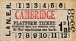 Railways across the country made a number of economy measures including withdrawal of passenger services. Cambridge escaped these although several lines in East Anglia did lose their passenger trains; Ely - St Ives, Somersham - Ramsey and Denver - Stoke Ferry to name three. Cambridge did see a number of economies, however. The LNER installed more efficient gas lighting at the station (replacing 'bat wing' burners with incandescent mantles), some track alterations and a number of economy measures on the Mildenhall branch including closure of some signal boxes and removal of Coligny-Welch distant signal lamps. It is surprising the Mildenhall and Kettering branch passenger services survived but, as we know, they did - at least for the time being. Railways across the country made a number of economy measures including withdrawal of passenger services. Cambridge escaped these although several lines in East Anglia did lose their passenger trains; Ely - St Ives, Somersham - Ramsey and Denver - Stoke Ferry to name three. Cambridge did see a number of economies, however. The LNER installed more efficient gas lighting at the station (replacing 'bat wing' burners with incandescent mantles), some track alterations and a number of economy measures on the Mildenhall branch including closure of some signal boxes and removal of Coligny-Welch distant signal lamps. It is surprising the Mildenhall and Kettering branch passenger services survived but, as we know, they did - at least for the time being.
Nevertheless, southern England began to recover somewhat quicker than the north so Cambridge escaped the worst of the depression and its proximity to London may have helped. As far as the railways and those interested in the railways were concerned, there was a number of events at Cambridge which no doubt provided a welcome distraction from the gloom.
In 1931 the LNER re-roofed the ex-GER engine shed and in 1934 built the famous coaling tower which greatly speeded up the coaling of locomotives. These coaling towers became a common sight at larger sheds across the country; that at March came to be known as 'The Wedge' due to its shape and the Cambridge coaling tower also came to be referred to by that nickname too. At the same time as the coaling tower was built, the turntable was replaced with a 70ft example.
An unusual event occurred on 22 May 1933 when Gresley's experimental locomotive No.10000 was seen at Cambridge en route to Doncaster from an exhibition at Southend.
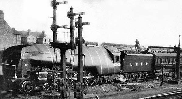
Photo courtesy The Gresley Society
Here she is at Cambridge North, taking on water on that occasion. She has used the goods roads avoiding the station. The two smaller signals, one of which is off, are shunt signals and do not apply to 10000. The electric motors which operate the signals can be seen towards the bottom of the posts. The photograph may have been taken from the steps of Cambridge North signal box and Mill Road bridge is to the photographer's left.
© National Railway Museum/SSPL
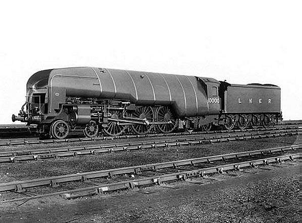
Above is an official photograph of Class W1 No.10000. Known as the 'Hush Hush' locomotive due to somewhat fruitless attempts to keep the project secret, she was also given the nickname 'The Galloping Sausage'. She was a 4-6-4 locomotive fitted with a Yarrow high pressure water-tube boiler and the idea was to produce a more thermally efficient locomotive. Gresley, it seems, got the idea from a similar experiment by the Delaware & Hudson Railroad in the USA. No.10000 made her appearance in December 1929 and although she achieved some 90,000 miles in service much of her time was spent in works for various problems, repairs and modifications. In late 1935 Gresley halted any further work on the project and No.10000 was rebuilt into conventional form but with A4 style streamlined casing. She retained her 4-6-4 wheel arrangement, Class and running numbers. A short British Pathé film of The Galloping Sausage at King's Cross can be seen here.
Photo
from Mike Morant collection
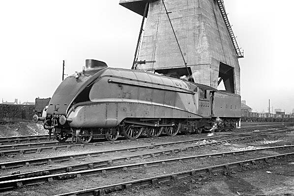
The rebuilt No.10000 on shed at Cambridge, above, on Sunday 21 November 1937. She had worked a local service from King's Cross, believed to be her first revenue earning trip since rebuilding.
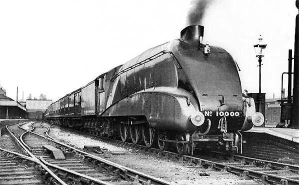
Photo courtesy The Gresley Society
Turned and watered, 10000 is seen in platform 2 at the head of the 2.6pm local back to King's Cross. Note the gas lamp on the right, with station name on the casement glass. Photographic evidence suggests this lamp for some reason lingered on after most others on the station (the exception being those on patform 6 cantilevered from the shed wall) had been replaced by the type mounted in harp-shaped frames. The structure far right is the water crane, complete with stove to prevent the water freezing. In 1951 60700, as she became under BR, was to have been named 'Pegasus' and Doncaster works cast the nameplates on 13 April that year. However, for reasons unknown the plates were never fitted and what happened to them is also unknown. In rebuilt form the locomotive had a successful career - apart from overturning following a derailment at Peterborough in 1955 caused by a fractured bogie frame - and was an occasional visitor to Cambridge on diverted East Coast trains and also appeared from time to time on fill-in turns
between King's Cross and Cambridge. She continued to appear at Cambridge until withdrawal from service in June 1959. The original Yarrow boiler outlived the locomotive by six years, being retained at Darlington works for various purposes until 1965. The locomotive's tender, however, lives on and is today paired with A4 60009 'Union of South Africa'. In the above photographs of her in rebuilt form, livery was garter blue. In original form she was in a green livery and she carried wartime black during WWII. The side valences were removed in 1942. Eventually she was to receive BR lined green livery, in the same style as the A4s.
On 7/8 May 1938 the LNER staged a locomotive and rolling stock exhibition in, photographic evidence suggests, the sidings west of the engine shed. A handbill for this event survives in the Essex Record Office as part of the Great Eastern No.Railway Society's collection but full details of what was exhibited are patchy. We do know Claud 8783 and B1 2818 were there to be admired along with a number of carriages containing displays and perhaps a cinema but other details have so far been elusive. There was possibly a Y5 'Coffee Pot' locomotive also present. The Cambridge University Railway Club (CURC) were, according to their records, involved and the LNER invited them to display a model railway layout but further information is lacking.
Locomotive No.8783 was one of two Clauds used for Royal train duties as and when required, the other being 8787. In June 1939 8783 was damaged in a level crossing accident at Hilgay, Norfolk. Both Royal Clauds survived into BR ownership, as 62614 and 62618 respectively and were withdrawn in 1959. The Claud Hamilton Locomotive Group plan to build a new Claud numbering it, as it happens, 8783.
On 24 August 1938 the by then preserved GNR Stirling Single No.1 operated a return trip from King's Cross to Cambridge. This was an excursion entitled 'The Old Flying Scotsman' and the train consisted of seven vintage GNR coaches. Passengers, or at least some passengers, were attired in Victorian clothes. The occasion was the fiftieth anniversary of the Railway Races to the North which saw the 'Flying Scotsman' reduce the King's Cross - Edinburgh time to 8½hrs. This was the 'Flying Scotsman' train, of course, not the A3 Class locomotive so named. No.1 also operated two King's Cross - Peterborough, on different days.
As we have seen, as part of the 1926 resignalling North and South boxes were relocated away from the platform ends. This enabled the main platform to be further extended and this is thought to have occurred c.1938. This took the platform to 1,650ft and it was to remain at this length until the 21st century.
From Railway Wonders of the World
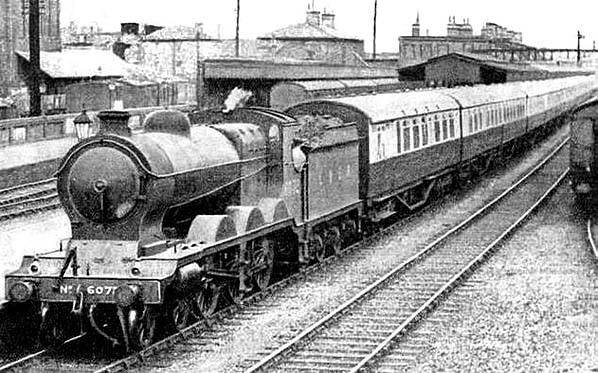
Above the unusual appearance of ex-Great Central B5 No.6072 at Cambridge can be seen in December 1935. The train is formed of LNER tourist stock in green and cream livery. This stock was built for excursion and charter traffic but details of this particular working are not known. The B5s were known as 'Fish Engines' because the initial batch was synonymous with the Grimsby fish trains and for this purpose some were allocated to Grimsby and Neasden. They could also be seen on passenger workings to / from Marylebone but the appearance of one elsewhere in southern England on a passenger train was rare. 6072 was withdrawn in August 1947 from Mexborough shed.
Two further events occurred at Cambridge during the 1930s which warrant more detail. These were the rubber-tyred Michelin railcar and the LMS articulated diesel multiple unit.
La Micheline and the Coventry Railcars
1. The Michelin Railcars
La Micheline, in English The Michelin, was the name applied to a series of railcars running on Michelin pneumatic tyres. The name seems to have applied more specifically to earlier types which resembled road lorries in both rigid and articulated form. Apart from initial experiments, such as that described below, the railcars were not converted road vehicles. Nor were they diesel railcars as some sources claim, they were petrol railcars.
The principle was pneumatic tyres mounted on wheels similar to those of road vehicles but bolted onto a steel disc which served as a flange. Thus the railcars offered smooth and near-silent operation with the added benefits of better acceleration and braking, due to the better grip offered by rubber, when compared to conventional steel railway wheels.
The idea is credited to Monsieur Edouard Michelin who, it was said, had problems sleeping on overnight trains due to track noise. Standard railway vehicles are far too heavy for pneumatic tyres, however, so Michelin realised the way forward was with lightweight railcars. To this end, a standard Renault car was converted during 1929.
The Paris - Lyon - Mediterranee Railway (PLM) was approached regarding trials, after the converted Renault had operated successfully in the Michelin works sidings at Clermont - Ferrand. The PLM, having composed itself following a mixture of horror and hysterics, agreed to trials on an isolated branch line in the Savoy Alps with a breakdown train in attendance. The latter transpired to be unnecessary and the trials were a total success to, apparently, the surprise of all concerned. It has to be said that credit must be given to the Michelin company for by 1931 they had produced an 18-seat railcar which was demonstrated, successfully by all accounts, between Paris and Deauville during that year.
By 1932 Michelin's Type 9 railcar had appeared and in that same year one of these was sent to Britain for trials. We know from surviving records that the railcar was in Britain by February 1932.
© National Railway Museum/SSPL
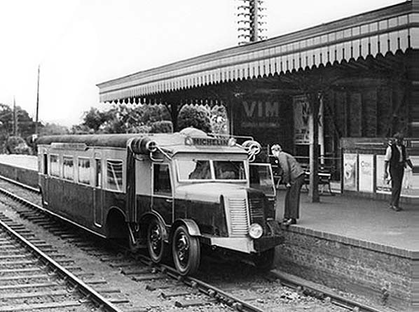
The above image shows the Type 9 railcar at Ascot, Southern Railway. It is known to have also operated in the Leamington Spa area and between Oxford (Rewley Road) and Bletchley. There is no record of this particular railcar operating to Cambridge. The railcar was articulated with a six-wheel bogie at the front and, despite appearances, a four-wheel bogie at the rear (earlier examples had a single axle at the rear). Brakes were Lockheed hydraulic, acting upon all wheels.
The power unit was constructed by Renault and the engine was a Panhard - Levassor sleeve valve petrol unit of 27 h.p. This figure was the RAC rating; a peculiar system devised by the RAC on behalf of the British government for taxation purposes. The calculation took into account only the cylinder bore diameter, not the swept volume of the pistons. The actual brake horsepower of this railcar engine would have been in the region of 80 - 85 h.p. at 2,500 - 3,000 r.p.m. Petrol engines were used because no diesel engine available at that time had a suitable power-to-weight ratio; in other words the then-available diesel engines were too heavy.
Sleeve valve engines are today museum pieces. The inlet and exhaust ports were controlled by cylindrical sleeves inside the cylinder bores and which moved up and down by means of cams. The best known names associated with sleeve-valve engines were Ricardo and Knight, the latter design being used by Daimler in its 'Silent Knight' engine. These engines, at the time, offered a number of advantages over other types but their oil consumption was necessarily heavy and vehicles so fitted were characterised by the haze of blue smoke which followed them everywhere they went.
Finding our way out of the smoke and returning to Ascot, we can see the Michelin name on a board mounted on the cab roof while the board at cantrail level on the passenger section states 'Running on Michelin Pneumatic Tyres'.. The radiator grille was a dummy; aircraft type radiators being fitted one each side of the cab roof. This in turn meant topping up of the coolant had to be done via a filler cap located on the cab roof. A four-speed manual gearbox was fitted and, with the obvious omission of steering gear, the driving controls were the same as those of contemporary road vehicles. A separate reverse gearbox was fitted to allow all four speeds of the main gearbox to be used when running in either direction and this bi-directional ability was the reason for the use of aircraft type radiators. Drive, it is believed, was from the engine to the centre axle with a roller chain connecting to the front axle with remaining axles therefore being purely load-bearing.
 Given that a separate reverse gearbox was fitted but that the cab and controls were otherwise similar to a road vehicle, quite how these railcars were driven in reverse is something of a mystery. A surviving French document suggests these railcars needed turning at the end of each trip, but some details of the rear end of the Type 9 are known.The body sides tapered inwards and the roof downwards to meet a door in the end of the body. In the upper part of the door was a two-piece window, the top section of which appears to have been hinged from the top. This top section had a windscreen wiper. On the left side of the body's rear end was a klaxon and on the right side a single headlamp. These items strongly suggest driving controls were fitted at the rear but bearing in mind the road vehicle type cab and controls at the other end, plus the articulation, quite what the precise arrangement was is difficult to comprehend. Also, driving controls immediately behind an opening door somehow seems rather unlikely. Given that a separate reverse gearbox was fitted but that the cab and controls were otherwise similar to a road vehicle, quite how these railcars were driven in reverse is something of a mystery. A surviving French document suggests these railcars needed turning at the end of each trip, but some details of the rear end of the Type 9 are known.The body sides tapered inwards and the roof downwards to meet a door in the end of the body. In the upper part of the door was a two-piece window, the top section of which appears to have been hinged from the top. This top section had a windscreen wiper. On the left side of the body's rear end was a klaxon and on the right side a single headlamp. These items strongly suggest driving controls were fitted at the rear but bearing in mind the road vehicle type cab and controls at the other end, plus the articulation, quite what the precise arrangement was is difficult to comprehend. Also, driving controls immediately behind an opening door somehow seems rather unlikely.
The passenger section of the Type 9 was a rudimentary affair; it consisted of a welded steel frame covered in canvas - presumably doped (a form of varnish) as in aircraft practice. Seating was for just 24 passengers, while heating was achieved by the simple expedient of passing air over the engine exhaust pipe. The railcar weighed, in working order, a mere 5 tons and was capable of speeds in excess of 60mph.
The lightweight construction was necessary due to the inability of the pneumatic tyres of the time to support the heavier loads usually associated with railway vehicles. Tyre-to-rail contact area was, of course, dictated by the width of the rail head, so to have wider tyres would have been pointless. It was for these reasons the railcars, once out of the early prototype stage, had 8, 10 and eventually 16 wheels. Tyre pressure is unclear, with accounts varying between 'low pressure' and 85psi. In the event of a puncture or loss of pressure, by 15 p.s.i., for other reasons, a warning horn would sound in the driving cab and pressure gauges were fitted to each wheel. If a puncture occurred the Type 9 had a wooden rim inside the tyre which prevented total collapse. Later railcars had steel rims inside the tyres while the Coventry railcars had solid rubber tyres within the pneumatic tyres. Changing a wheel was accomplished in exactly the same way as on a road vehicle with spare wheels, jacks and other tools being carried.
On plain track, tyre wear was said to be negligible but points and crossovers took their toll of the tyres. Michelin themselves stated their 'Super Low Pressure' tyre had a service life of over 18,500 miles while other sources state the tyres were good for an average of 20,000 miles. Such a mileage was good by the road vehicle standards of the time but the greater mileages railway passenger vehicles are expected to achieve meant tyre changing would have been necessary at frequent intervals. Even a passenger train, or railcar, operating only branch and local services would be expected to cover, on average, 2,000 miles per week, so tyre replacement would be required every nine or ten weeks. However, we must be careful not to judge too harshly the engineering standards and expectations of almost a century ago with those of today.
Before we leave the Type 9 railcar behind, it should be mentioned that the above image was chosen despite several others showing this railcar in better detail existing. These railcars were built with continental-style low platforms and ground-level access in mind, so quite what the practice was at 3ft high British platforms is difficult to imagine and the Ascot image illustrates the problem very well. At least the cab doors can apparently be opened when the railcar was at a platform. In any event, the Type 9 was in Britain only for test purposes and there was never any intention to operate it in regular passenger service.
Photo
from Mike Morant collection
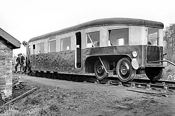
A rare view of the Michelin Type 9 railcar's rear end, said to have been taken at Coventry in April 1932. Visible are the klaxon horn, single headlamp and windscreen wiper on the end door. Despite these embellishments it remains difficult to see how these railcars could be driven from the rear. Was there really linkage to the road vehicle type controls at the other end? Was there really a driving position behind the opening end door? These are questions to which answers have proved evasive. The large disc on the near mudguard/splasher presumably deputises for a tail lamp. It is not known what the cranked bar apparently protruding from the rear of the vehicle is. This view gives an idea of the construction of the passenger section of these contraptions. Bearing in mind the body was of doped canvas on a lightweight tubular frame, the passenger section was little more than a tent on wheels. Crash Worthiness? Minus ten perhaps.
 The Type 9 was returned to France at an unknown date towards the end of 1932 or in early 1933. At this point there is some confusion over what happened next. Two photographs exist of a Type 11 railcar; one taken at Leamington Spa and the other at Harwich, with the latter taken just after the railcar had been unloaded from the Dunkirk ferry. The Type 9, as we have seen, entered Britain via Tilbury and a check on freight train ferries at that time shows the port had indeed changed from Tilbury to Harwich during 1933. Therefore we know the Type 11 railcar entered Britain no earlier than 1933, so it is quite likely the Type 11 was sent from France as a swap for the Type 9 which had arrived the previous year. The Type 9 was returned to France at an unknown date towards the end of 1932 or in early 1933. At this point there is some confusion over what happened next. Two photographs exist of a Type 11 railcar; one taken at Leamington Spa and the other at Harwich, with the latter taken just after the railcar had been unloaded from the Dunkirk ferry. The Type 9, as we have seen, entered Britain via Tilbury and a check on freight train ferries at that time shows the port had indeed changed from Tilbury to Harwich during 1933. Therefore we know the Type 11 railcar entered Britain no earlier than 1933, so it is quite likely the Type 11 was sent from France as a swap for the Type 9 which had arrived the previous year.
On 16 February 1932 Commercial Motor magazine published an article on the Type 9 railcar. While such articles are now a valuable historical record, the Commercial Motor article, in typical journalistic fashion, is rather dubious in respect of accuracy. It was claimed the railcar whizzed along the Oxford - Bletchley line at 92mph fully loaded; whilst that figure is specific rather than given as, say, 'around 90mph' which would suggest guesswork, it is doubtful the Type 9 could attain such a speed; 55 - 60mph being the usually quoted figure. The article also states the railcar was suitable for 'oil or electric' propulsion. 'Oil engine' is a now somewhat archaic term for a diesel engine and as we have seen it was not possible at that time to equip these railcars with diesel engines. Nevertheless even today some people, who in many cases ought to know better, still describe these railcars as 'diesel'. Electric propulsion was also a somewhat ridiculous claim as rubber tyres would not provide the current return path necessary with overhead wire or conductor rail power supplies. Battery power would in theory have been possible but the ever-present problem of battery weight would have made it completely impractical for the Michelin railcars which through necessity had to be lightweight.
On 19 March 1932 the Stephenson Locomotive Society organised a return trip with the Type 9 between Bletchley and Oxford but no details are known. Another trip was arranged for 11 June between Ascot and Alton and return.
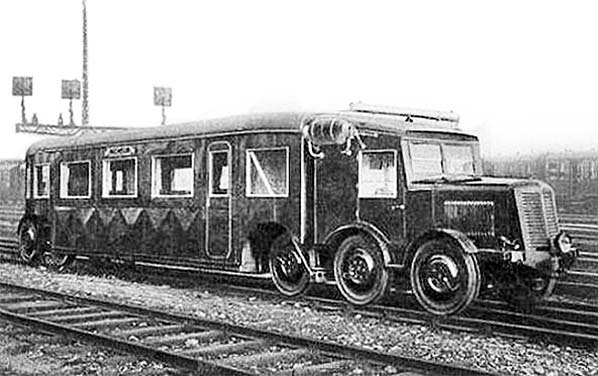
Above is a postcard view of a Type 11 railcar in France and this could well be the same railcar that was sent to Britain. Whilst similar to the Type 9, the Type 11 had a few differences; a more powerful engine was installed; the cab differed in detail and an all-over livery was applied (possibly a deep shade of red). There was also the addition of the tubular object on the cab roof; this was in fact a header tank for the engine cooling system and topping-up was achieved by removing a cap of which there was one at each end of the tank.
Little is known of the Type 11s time in Britain, but it appears not to have been tested on the Southern Railway but instead pottered around the Leamington Spa area and the Oxford - Bletchley line much the same as the Type 9 had later done. There is some very scant evidence that it made one trial run to Cambridge. The Type 11 returned to France after a very short stay in Britain. Tyre size was 910mm x 125mm and this seems to have been consistent for all standard gauge Michelin railcars.
The confusion, mentioned earlier, comes from the Type 11 often being muddled with a Michelin Type 22 railcar which was also sent over from France, in 1934. This shuttling of railcars back and forth suggests Michelin was keen to ensure Britain's railways were kept up to date with their developments. The Type 22 railcar was the example known to have run trials to Cambridge and for which photographic evidence exists.
© National Railway Museum/SSPL
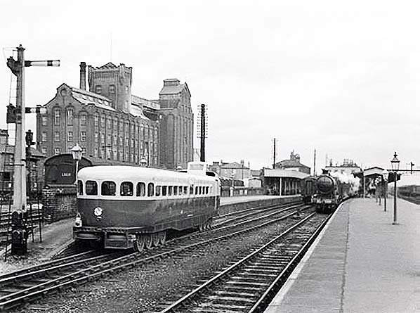
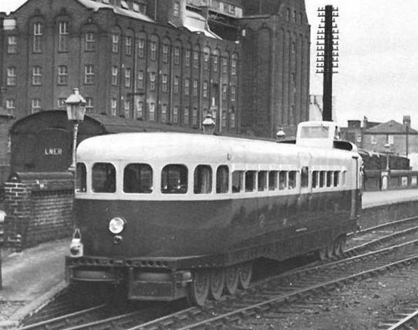
Above the Type 22 is seen arriving at platform 3 of Cambridge station in 1935, having run from Bletchley or Oxford. There was a number of differences between this and the Coventry railcars, as we will see in due course. The image shows just how far the design had evolved over a very short space of time. The French Type 22 was a 56-seat railcar carried on two 8-wheel bogies and powered by a Hispano-Suiza 240 h.p. petrol engine. Two spare wheels and what is assumed to be a toolbox can be seen underneath the end of the body. Passenger access was via a single-leaf air-operated sliding door on each side of the body in the centre. A toilet compartment was provided and at the powered (No.1) end was a luggage compartment accessed by roller-shutter doors. Braking was air-assisted hydraulic, acting on all wheels.
Hispano-Suiza (HS) was a Barcelona based company with tentacles in France and better known for their large, upmarket cars and their involvement in the aircraft industry. The company still exists but is, at the time of writing, known as Safran following a series of takeovers and mergers. For use in the Michelin railcars, HS developed a lightweight and rather neat engine known as the Type 86. It was a 12 cylinder horizontally-opposed unit using much aluminium alloy in its construction and designed to sit transversely in the bogie frame, drive to the wheels being via fluid coupling and self-changing gearbox to one axle and thence via roller-chain to an adjacent axle.
 Perhaps the most striking feature was the 'conning tower' driving position. This meant only one driving position, and thus one set of controls, was necessary. The drawback with this arrangement was the driver needing to turn one way or the other according to direction of travel. To access his position, the driver had to first climb onto a raised platform and then onto his seat which was cantilevered from safety railings around the edge of the platform. The precise method of control with railcars using the Type 86 engine which, being bogie mounted, moved relative to the body, is not clear, but other railcars used a more conventional HS V12 engine* mounted in the body underframe and in these cases control was via levers projecting up into the conning tower. The official term for the conning tower seems to have been "Driver's platform". *This was a bored-out Hispano-Suiza J12 automotive engine. Perhaps the most striking feature was the 'conning tower' driving position. This meant only one driving position, and thus one set of controls, was necessary. The drawback with this arrangement was the driver needing to turn one way or the other according to direction of travel. To access his position, the driver had to first climb onto a raised platform and then onto his seat which was cantilevered from safety railings around the edge of the platform. The precise method of control with railcars using the Type 86 engine which, being bogie mounted, moved relative to the body, is not clear, but other railcars used a more conventional HS V12 engine* mounted in the body underframe and in these cases control was via levers projecting up into the conning tower. The official term for the conning tower seems to have been "Driver's platform". *This was a bored-out Hispano-Suiza J12 automotive engine.
From the image of Cambridge we can see the conning tower, as we will call it, is located more or less along the body centre line. Railcars using the underframe-mounted V12 engine had, by necessity, the conning tower located to one side of the body and this was the case with the Coventry railcars.
All the railcars had a radiator mounted in a conventional position, as per road vehicles, above the frames at the No.1 end. For running with No.2 end leading the radiator had shutters which closed and instead air was drawn in via roof-mounted scoops. These scoops can be seen either side of the conning tower in the Cambridge image. The Coventry railcars used a similar arrangement but which differed in detail.
The Coventry cars had 'Coventry Railcar' monograms on their body sides. The 'Cambridge' Type 22 railcar also had monograms which appear to have stated 'Pneumatic Railcar' but surviving photographs are too unclear to be certain.
© National Railway Museum/SSPL
Above is an enlarged detail from the previous image. The spare wheels and toolbox can be better seen as can the monograms on the side of the railcar. Although the railcar has head and tail lights fitted, an oil lamp is still carried irrespective and as required by regulations. The railcar is almost certainly stationary and posed for the photographer; the driver can be seen up in his conning tower but he appears to be sitting and facing the direction of travel. French-built railcars are known to have had the driver sitting sideways and thus needing to turn his head to face the direction of travel.
Livery was red and cream but the red continued round the car ends at waist level, unlike on the Coventry cars where it swept down at each end. Note the passenger doors slide into pockets within the body panels whereas on the Coventry cars the doors were mounted externally in a similar manner to those of modern tube rolling stock.
2. The Coventry Railcars
Grace's guide to British Industrial History. from The Engineer
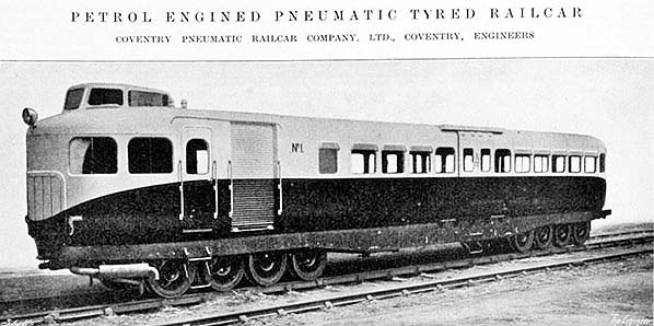
Above is Coventry Railcar No.1, the other being, well, No.2. Photographs exist of both railcars bearing their respective numbers but they are sometimes misdescribed as No.2 and No.3 with the 'missing' No.1 assumed to be a convenient reference to the Cambridge Type 22 railcar. At around the time the Coventry cars were introduced, 1935, the Type 22 railcar simply disappeared. Probably, the Coventry cars rendered it redundant and it returned to France.
The Coventry Pneumatic Railcar Company was a joint undertaking between the LMS, Michelin and Armstrong-Siddeley (AS) of Coventry. Like Hispano-Suiza, AS was also a producer of upmarket cars as well as being involved in the aircraft industry. After the Second World War AS became part of the Bristol-Siddeley-Maybach concern, producing Maybach engines under licence for some of British Rail's diesel-hydraulic locomotives.
For the Coventry railcars, AS had developed their own V12 petrol engine; a 13 litre unit giving 275h.p. at 3,000r.p.m. It weighed a mere 1,000lb and the complete railcars weighed, in working order, a very commendable 6½ tons. However, a drawing exists clearly intended to show a Coventry railcar (it is titled as such) and this states the weight in working order as being a fraction over 8 tons. An Ogden's cigarette card depicting a Coventry railcar gave the tare weight as 9 tons or 14 tons fully laden. The drawing also shows the conning tower located just off the centre line of the car, as per the 'Cambridge' Type 22, and with the roof-mounted air scoops also as per the Type 22. As pictures of the Coventry railcars show, the design as-built was rather different and the reasons for the changes are not known although we can guess they may have been connected with the decision to use the V12 engine instead of the HS horizontally opposed unit.
Mentioned earlier was the fitting of solid rubber tyres within the pneumatic tyres of the Coventry railcars. This allowed the railcars to continue in service with a punctured tyre until a convenient time to change the offending wheel arose, although this would presumably have required reduced speed. inner tubes were also fitted, as was the norm at the time, and this applied to all the pneumatic railcars. The inner tubes differed to those used on road vehicles because of the need to accommodate the anti-collapse rims or, in the case of the Coventry railcars, the inner solid tyres. As far as can be ascertained regarding the Coventry railcars, the inner tube was of a 'U' cross section and was fixed and sealed to the wheel rim and with the inner solid tyre inside the tube and the pneumatic tyre outside. Thus when a puncture occurred, the inner tube deflated and the railcar ran on the inner solid tyre. This means air would have provided nothing more than a cushioning layer between inner and outer tyres - very different indeed to the much simpler system of tubeless tyres were are familiar with today on road vehicles.
The Coventry railcars were 55ft long overall, 9ft wide and 12ft high from rail to top of conning tower. The conning tower had, of course, to fit within the British loading gauge and, like the Type 22, the Coventry railcars had to suit the height of British station platforms. It was for those reasons the railcar bodies were rather squat, giving the illusion they were wider than they actually were. For their time and to British eyes, they were ultra-modern in appearance and their livery, said to have been crimson lake and a light shade of cream, while not exactly new (the LNWR had used a similar coaching stock livery) must have been quite eye catching.
Coventry No.1 made its debut on 20 June 1935, with No.2 following soon afterwards. One, at least, of the Coventry cars is known to have undertaken trial runs between Rugby and Market Harborough (part of the now-closed Rugby - Seaton - Stamford/Peterborough route) and also between Oxford and Cambridge. Details of the latter are, however, vague and it is unclear if either Coventry car actually ran as far east as Cambridge. Most photographs of the Coventry cars depict them in service in the Coventry/Kenilworth / Leamington Spa area.
No.1 is known to have then made a press run from Rugby to Wansford (near Peterborough) and return, following which both railcars operated services in the Coventry - Leamington Spa - Rugby - Nuneaton area. The services were advertised by handbill and slotted-in between regular timetabled services operated by proper trains. They were based at Rugby, a 3-road part of the shed being reserved for them. Possibly this was done partly to keep them away from steam locomotive grime but mainly to keep the fuel supply, petrol, away from the risk of fire.
In time, the Coventry/AS engines became problematic and at least one railcar was given a Hispano-Suiza engine instead. This was presumably a J12 as fitted to the later Michelin railcars.
© John Alsop Collection
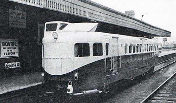
Above Coventry No.2 is seen at, it is thought, Leamington Spa (Avenue) in 1936. The side position of the conning tower can be seen, this being necessary because of the underframe-mounted V12 engine. The exhaust silencers can be seen, as they can in the previous image; there was one for each bank of cylinders and located conspicuously but neatly under each side of No.1 end. Another difference to the Michelin Type 22 was the two-leaf sliding passenger doors mounted externally of the body. The oil tail lamp was a mandatory requirement despite these railcars being fitted with electric lighting clusters. Mentioned earlier was the air scoop arrangement which differed to that of the Type 22. The scoop was raised and the radiator shutters were closed when the railcars ran with No.2 end leading. With No.1 end leading the radiator shutters opened and the scoop closed. When closed, the scoop was flush with the roof. There has been some suggestion that in the Coventry cars the driver was able to sit actually facing the direction of travel and this does appear to be the case from photographs of the cars in service. If so, the arrangement of the driving seat and controls has to be questioned but details are not known.
The railcars were popular with the travelling public and, providing it wasn't a hot day, with the crews too. The railway authorities, however, quickly lost interest and the scheme was abandoned in 1937. Later that year the Coventry railcars were taken to the Michelin premises at Stoke-on-Trent and there they lingered until 1945 when they were scrapped. All that remains of them is one wheel, in the National Railway Museum having been presented by Michelin.
All the lightweight pneumatic railcars had their drawbacks. The necessary light weight prevented the use of proper buffing and drawgear; their near-silent operation was seen as a hazard to track workers used to the sound of steam locomotives and the rubber tyres could not operate track circuits (track circuiting is a system whereby a small electric current is passed through the rails and when this is short-circuited by conventional steel wheels the instruments in signal boxes are actuated. The Coventry railcars were fitted with skates to eliminate this problem but apparently they proved unreliable). One perpetual problem with any lightweight railway vehicle is the relatively high cost of construction and of repairs following accident damage; British Railways was mindful of this problem many years later with their Wickham-built diesel multiple units and railbuses.
It is said that the Coventry railcars were prohibited from running during the hours of darkness and during fog due to safety concerns. The hours of darkness were, of course, known in advance and as the railcars were not guaranteed to run this would not have caused any problems. Fog, however, is less predictable so must have caused some cancellations at short notice. It is not known if these restrictions applied only to the Coventry railcars or all those which operated in Britain but it is likely it was all of them. Another aspect for which the answer is not known is whether the safety concerns were genuine or part of an attempt by a disinterested LMS to kill off the project, but given that the railcars were quiet running and very dodgy where track circuits were concerned we can probably safely assume the concerns were genuine.
Despite the drawbacks the railway authorities in Britain were quick to point out, the main reason for their demise in Britain was probably the Second World War. As war clouds gathered, industry, including Armstrong-Siddeley, was gearing up to rearmament and other war production and, as happened with the LMS articulated diesel multiple unit, experimental projects were very much pushed into the background. The success of the Great Western's AEC diesel railcars may also have influenced the decision to abandon the concept.
Drawbacks or no drawbacks, war or no war, the French, as might be expected, took a totally different approach and over one hundred Michelin railcars gave many years of good service in France and her colonies. Others eventually found their way to other parts of the world and in the USA the Budd company produced them under licence. Today several examples can be seen in museums while at least one, in Madagascar, is still operational as of 2015.
On a brighter note, several Metro systems operate rubber-tyred trains. Paris, Mexico City and Santiago have some lines operated in this manner while the Montreal Metro is currently operated entirely by rubber-tyred trains. The rubber-tyre principle offers distinct advantages in urban areas, especially where lines are underground, where reduced noise and vibration are most desirable. Metro systems are also usually self contained and operate, engineering trains excepted, only passenger trains of lightweight fixed formation stock, therefore the problems of operating rubber-tyred trains on main lines where they have to integrate with conventional rolling stock are eliminated. However, while the rubber tyre principle remains on these modern metro systems, the precise technology is a long way from the Michelin railcars of yesteryear.
Click here to continue Part 3: The Big Four Period
| Last
updated: Sunday, 07-Apr-2019 10:53:58 CEST |
© 1998-2015 Disused Stations
| |

 Gresley's influence was therefore felt at Cambridge long before the LNER came into existence with his articulated twin sets, K3 and N2 locomotives among others. He was later to leave his mark on Cambridge in a bigger way with his B17 locomotives, also known as the 'Sandringham' or 'Footballer' Class. Sir Nigel Gresley became so-titled in 1936, having been knighted by King Edward VIII who was to abdicate later that same year. He died on 5 April 1941 at Watton-at-Stone, Hertfordshire, aged 64 years. Gresley was succeeded by Edward Thompson as CME until 1946 when Arthur Peppercorn took over until nationalisation.
 BPRS supplied Cambridge with lower quadrant signals using tapered arms, in metal, with strengthening corrogations rather than flanges as found on other signal arms. These BRPS arms were said to be of a design originally produced for Australia. Electrically operated ground signals (shunt signals) were also provided and certain of these were fitted with semaphore arms, as opposed to discs, made from vulcanised rubber to minimise the possibility of damage resulting from clearance issues. It was these two features which made this signalling unique to Cambridge.
 Cambridge also had certain sets of points equipped with gas heating, to prevent the moving components freezing during periods of low temperatures. These consisted of tubes a few feet long with burner jets at intervals along their lengths, the flames being directed onto the outer faces of the rails.
 Photo by
  Royal trains, a common sight at Cambridge, did not lower the tone by using the goods roads but instead always passed through Cambridge via the platform roads. Members of the Royal Family often visit Cambridge by train and have done so since 1847, usually in connection with the university, as well as passing through en route to Sandringham following Queen Victoria's purchase of Sandringham House in 1862. Today, with these journeys being only short runs from London, especially if only travelling to Cambridge, the royal train is seldom used and it is common for The Queen and other members of the Royal Family to travel by timetabled service train; an ordinary outer-suburban electric multiple unit. This is normally from King's Cross as this avoids the formalities needed for the Monarch to enter the City of London in which Liverpool Street station is located. Also, the vast majority of trains to King's Lynn (now the nearest station to Sandringham) nowadays run to and from King's Cross.
 The signals seen above were familiar to generations of railway fans who would congregate by the railings on the left. Some appear to be present in the image. Note the steps leading down from Hills Road; these disappeared when the bridge was rebuilt c1960 leaving anybody who wanted access to the railings or the road behind them, which went to the goods sheds, to make a detour via the Hills Road / Cherry Hinton Road junction at the foot of the bridge.


 By the time the Sentinel and Clayton cars (of which the latter had a rather disfiguring external coal bunker) appeared, steam railcars had already become something of relics from the past but the Sentinels offered a number of advantages over earlier types and gave the steam railcar a second fling. The Sentinel Waggon Works, Shrewsbury, eventually became part of Rolls-Royce and under that guise produced their well-known range of diesel shunting locomotives which can still be seen pottering around today.
 Railways across the country made a number of economy measures including withdrawal of passenger services. Cambridge escaped these although several lines in East Anglia did lose their passenger trains; Ely - St Ives, Somersham - Ramsey and Denver - Stoke Ferry to name three. Cambridge did see a number of economies, however. The LNER installed more efficient gas lighting at the station (replacing 'bat wing' burners with incandescent mantles), some track alterations and a number of economy measures on the Mildenhall branch including closure of some signal boxes and removal of Coligny-Welch distant signal lamps. It is surprising the Mildenhall and Kettering branch passenger services survived but, as we know, they did - at least for the time being.


 Given that a separate reverse gearbox was fitted but that the cab and controls were otherwise similar to a road vehicle, quite how these railcars were driven in reverse is something of a mystery. A surviving French document suggests these railcars needed turning at the end of each trip, but some details of the rear end of the Type 9 are known.The body sides tapered inwards and the roof downwards to meet a door in the end of the body. In the upper part of the door was a two-piece window, the top section of which appears to have been hinged from the top. This top section had a windscreen wiper. On the left side of the body's rear end was a klaxon and on the right side a single headlamp. These items strongly suggest driving controls were fitted at the rear but bearing in mind the road vehicle type cab and controls at the other end, plus the articulation, quite what the precise arrangement was is difficult to comprehend. Also, driving controls immediately behind an opening door somehow seems rather unlikely.
 The Type 9 was returned to France at an unknown date towards the end of 1932 or in early 1933. At this point there is some confusion over what happened next. Two photographs exist of a Type 11 railcar; one taken at Leamington Spa and the other at Harwich, with the latter taken just after the railcar had been unloaded from the Dunkirk ferry. The Type 9, as we have seen, entered Britain via Tilbury and a check on freight train ferries at that time shows the port had indeed changed from Tilbury to Harwich during 1933. Therefore we know the Type 11 railcar entered Britain no earlier than 1933, so it is quite likely the Type 11 was sent from France as a swap for the Type 9 which had arrived the previous year.

 Perhaps the most striking feature was the 'conning tower' driving position. This meant only one driving position, and thus one set of controls, was necessary. The drawback with this arrangement was the driver needing to turn one way or the other according to direction of travel. To access his position, the driver had to first climb onto a raised platform and then onto his seat which was cantilevered from safety railings around the edge of the platform. The precise method of control with railcars using the Type 86 engine which, being bogie mounted, moved relative to the body, is not clear, but other railcars used a more conventional HS V12 engine* mounted in the body underframe and in these cases control was via levers projecting up into the conning tower. The official term for the conning tower seems to have been "Driver's platform". *This was a bored-out Hispano-Suiza J12 automotive engine.


 Home Page