Before we return to Cambridge, we will take a trip to the Yunnan Province of China.............
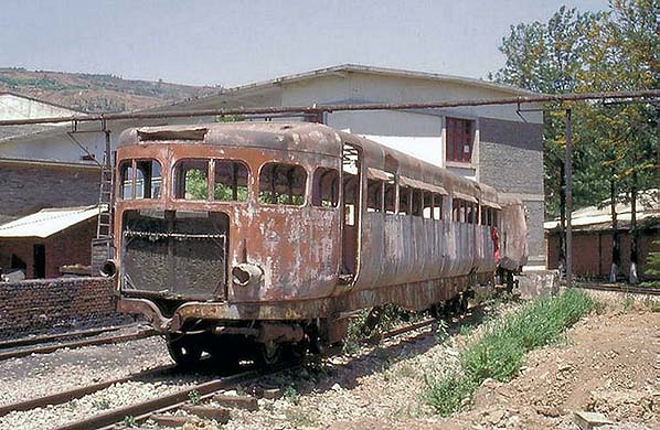
This picture and the five below are by Robert von Hirschhorn (railasia) from his Flickr photostream. Reproduced with permission
............where this derelict metre gauge example was photographed on in April 1999. This and the following images are worth including as they provide a rare insight into how these railcars were constructed. The example pictured is a single-ended type with a conventional driving cab and was new in 1936. A small trailer was also provided, this too running on pneumatic tyres. The railcar operated on the Kunming–Hai Phong Railway which, it so happens, was built by the French.
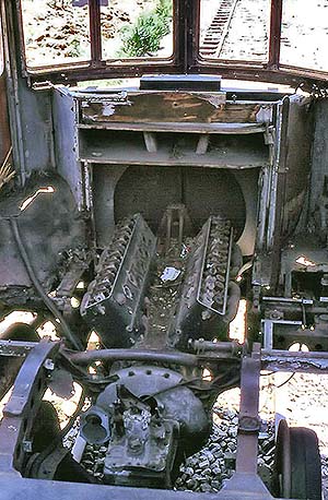
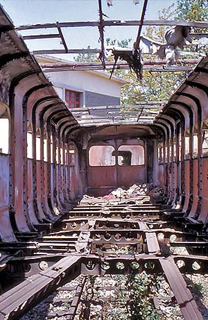 What is left of the railcar's interior is seen left and is looking towards the rear of the car. Note the thin section of the underframe members and the holes to help reduce weight further
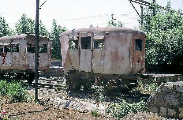
Below the battered and rather comical little trailer on its four-wheel pneumatic-tyred underframe is seen. The trailer would almost certainly be unbraked other than, perhaps, a handbrake, while coupling to the railcar appears to be via a simple Link and Pin arrangement.
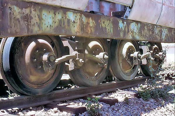
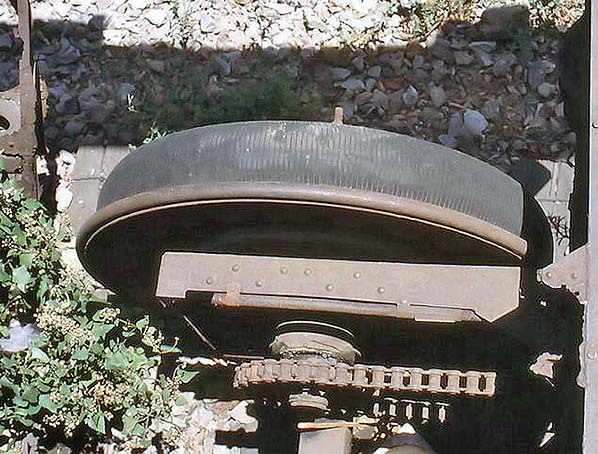
The third picture is seen one of the railcar's 8-wheel bogies. The wheel nuts can clearly be seen, as can the leaf spring and swing link suspension arrangement. The tyres still show the original tread pattern but there is no obvious signs of any pressure gauges on the wheels.
The fourth is a view, through a convenient hole in the floor, of a wheel and tyre. The steel flange can clearly be seen. This is a powered axle and also visible is the roller chain connecting to the adjacent axle. The chain appears rather feeble for the job it had to do; in theory the connected axles would rotate at equal speed but in practice any variation in tyre pressures or wear would cause a rotational speed difference resulting in undue stress in the chain.
 As far as is known, there was no means provided to compensate for any variation in axle rotational speeds. Nevertheless, no reports have come to light concerning problems with, or failures of, the chains.
The final picture (right) shows the railcar engine, or what is left of it, in its position mounted on the underframe. This is the V12 engine which, for all intents and purposes, superceded the bogie-mounted 12 cylinder horizontally opposed Type 86 unit. When complete, the V12 would project well up above floor level and would be covered by a cowling which curved downwards over the engine. The driving position was to the right of the engine and in the foreground part of what remains of the transmission can be seen.
Whilst the engine is incomplete, enough of it has survived to tell us the engine is almost certainly a Hispano-Suiza J12.
Since these photographs were taken, the railcar and trailer have been restored and a very fine job has been done too. It can now be seen at the Yunnan Railway Museum, Kunming.
We will now take a look at another 1930s visitor to Cambridge which was more conventional yet equally as revolutionary for its time.
The LMS Articulated Diesel Multiple Unit
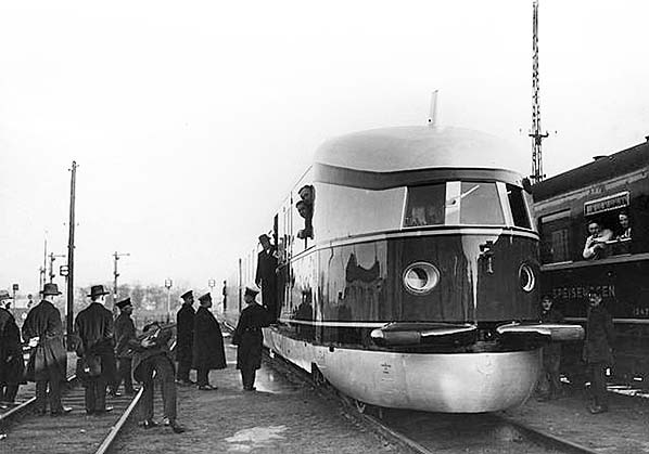
Photo from Bundesarchiv, reproduced under creative commons licence
Said by some to have been the inspiration behind the LMS diesel unit, above is the Class SVT 877 diesel-electric unit of the Deutsche Reichsbahn known as the 'Fliegender Hamburger'; in English, 'Hamburg Flyer' or its better known name 'The Flying Hamburger'. Nothing whatsoever to do with fast food being thrown out of a car window, the unit operated what was the world's fastest regular railway service at that time between Berlin Lehrter Bahnhof* and Hamburg Hauptbahnhof; covering the 286 kilometres in 138 minutes The picture was taken at the former station in December 1932 and the unit entered regular service on 15 May the following year. Built by Waggon und Maschinenbau AG, the unit had a Maybach G05 V12 engine at each end driving DC generators and traction motors. A two-car articulated unit, it seated 102 passengers and was capable of 160kph (almost 100mph). It appears to have been entirely successful but was to remain a one-off, although other units were developed from it; one of which ended up as an official train of the former GDR (East Germany) government and was not withdrawn until the 1990s. It is now on display at Leipzig Hauptbahnhof. The SVT 877 was stored during the war years but otherwise remained in service until 1957, by then numbered VT 04 000. The unit is now at the Deutsche Bahn Museum, Nuremberg, but is incomplete.
*Berlin Lehrter Bahnhof itself has an interesting history and its site is now occupied by the modern Berlin Hauptbahnhof. The history can be read here.
Back in England, at Derby, having gained some experience with internal combustion railcars in the form of railbuses 29950 - 2, the Michelin / Coventry cars and the English Electric diesel railcar 'Bluebird' which had also been tried on the Oxford - Bletchley line, the LMS was keen to produce its own lightweight self-contained diesel train as opposed to railcar or railbus. What emerged from Derby in February 1938 was somewhat different from what the Germans had so successfully introduced but common features were the use of multiple engines (then still a fairly new concept), articulation and the streamlined bodywork. The latter, however, as on the GWR diesel railcars, was the fashion in the 1930s so it should be no surprise that the LMS unit appeared in this style.
In Northern Ireland the LMS owned the railways which were operated under the NCC (Northern Counties Committee) banner. In 1934 the LMS had introduced railcar No.2, followed by Nos 3 and 4 in 1935 and 1938 respectively. They were ugly machines and, like certain of the Michelin railcars, had a 'conning tower' driving position. The body style differed between No.2 and the remaining pair but their diesel-hydraulic power train was identical to that ultimately used in the LMS Derby 3-car unit.
 During much of the 1930s, Tommy Hornbuckle was Chief Technical Assistant to the LMS Chief Mechanical Engineer; from January 1932 this was William Stanier. From the Hornbuckle Archive at the National Railway Museum it is clear Hornbuckle was enthusiastic towards non steam traction and his notes from 1936 mention a 3-car articulated diesel unit but with the interesting addition "and / or a 2-car" (of same). What appeared early in 1938 was, of course, a 3-car unit but it is widely acknowledged that a second unit was planned. Perhaps the 'and / or a 2-car' was to have been the second unit but the Second World War brought the scheme to a halt and in the event Hornbuckle left railway service in 1939 so we can only speculate at what might have been.
So what emerged from Derby could be said to have been not entirely innovative; the power train was that as used on NCC Nos 2 - 4 and was similar, but not identical, to that of railbuses 29950 - 2 while streamlining happened to be the fashion of the time. The real novelty, at least for Britain, was the multi-underfloor-engine, multi-carriage, self-contained diesel unit concept. In view of the aforementioned events, it is reasonable to suggest any similarities to the 'Flying Hamburger' were mere coincidence and any supposed inspiration from it was assumed rather than actual. the 'Flying Hamburger' was built before the Nazi Party came to power in Germany but entered service after the regime had taken office. Like the autobahn network which was in fact a project of the Weimar government, the Nazis were very good at taking credit for things which it was not in truth entitled to do and using them for propaganda purposes. Thus the 'Flying Hamburger' was well publicised both inside and outside Germany and this may have had some bearing on the British media assuming a connection between events on the Reichsbahn and the LMS.
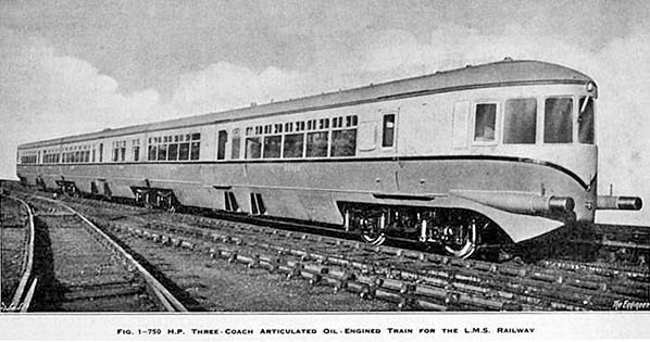
The Engineer, 1 April 1938.
The above image comes from an LMS official photograph. It is not of the best quality but worth including as it shows the unit with its side valances still in position. As we will see later from the Cambridge Daily News image caption the media, the public and the railway enthusiast fraternity gave these non-steam projects only a passing interest as though they were mere fads which would eventually go away. Notwithstanding this, a few mysteries concerning the LMS unit remain unexplained but on the plus side a lot of more important information is available to us.
The unit consisted of driving motor cars 80000/2 and non driving motor car 80001, the latter being the centre car.
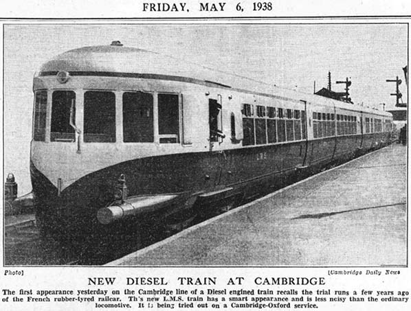
© The Cambridgeshire Collection
The unit above is at platform 1 of Cambridge station and 29 June 1938 a number of trial runs were made from Derby to Euston, Rugby, Darley Dale, Burton on Trent, Lincoln, Gloucester and the Lickey Incline to name a few. Reliability trials commenced on 5 May between Oxford and Cambridge and it was during one of these trials that the above photograph was taken. There were a number of failures and other problems, including one on 9 May with axle trouble and another on 15 June which involved failure at Potton with gear selection problems. Designed for a top speed of 75mph, the unit was capable of exceeding this and attained 82mph on one test run between Euston and Tring. The unit was sent to Wolverton for modifications on 29 June.
The caption with the above image is all the Cambridge Daily News had to say on the subject. 'Smart appearance' and 'Less noisy than an ordinary locomotive' is a quite feeble effort which suggests the newspaper struggled to find something to say and highlights well the mere passing interest these projects attracted outside of the railway and associated industries. Fortunately the technical press of the time provided much more comprehensive information. The unit is in its original condition with valances below the solebars; these later being removed due to engine overheating problems. The lamps on the buffer stocks suggest the unit had just arrived at Cambridge when the photograph was taken.
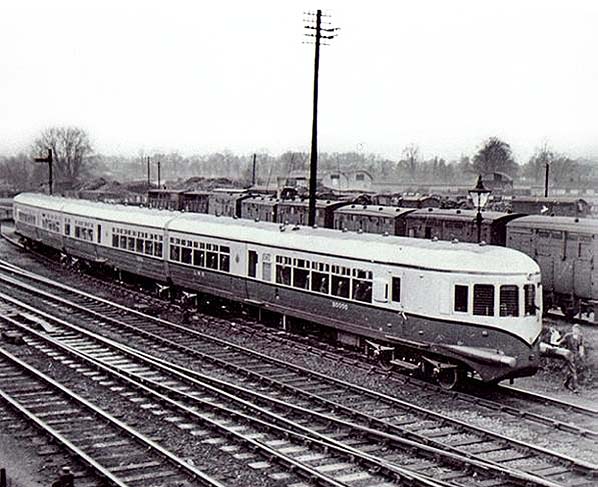
© The Cambridgeshire Collection
Above the LMS three-car articulated unit can be seen in the siding immediately south of Hills Road bridge, Cambridge. The unit had returned from Wolverton to recommence reliability trials on August 4th 1938. By this time the side valances had been removed and together with an improved design of air scoop for the radiators the engine overheating problem had been cured. Removal of the valances actually, it could be argued, made the unit look a little more modern. Note the large number of horse boxes and, probably among them, SCV's (Special Cattle Vans) in the LMS sidings behind the diesel unit. Three of the 1926 point motors and one shunt signal can also be seen. The above and following images are believed to have been taken in December 1938, by which time the unit had entered passenger service; this occurring on and from 5 September.
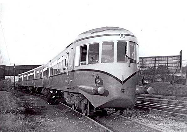
© The Cambridgeshire Collection
Above is looking north towards Hills Road bridge and shows the other end of the unit. A member of staff, probably the driver, is crouched down doing something to one of the engines. As on what we now call BR's 'First Generation' DMUs, the engines of the LMS unit could be started or stopped locally and individually.
When the unit emerged from Derby C&W brand new, livery was Post Office red below the waistband and silver above, including the roof, with black lining at the waistband. Prior to entering passenger and probably while the unit was at Wolverton, the livery was altered to cream between waistband and cantrail with the other colours remaining as before. Although it is not obvious from the newspaper image above, the waistband lining was present from new. The lining is curious; close examination suggests it might have actually been red-black-red or gold-black-gold rather than the solid black suggested by photographs.
A common myth surrounding the LMS unit concerns its buffers. It is often claimed the unit was fitted with conventional buffers at some point later in its short career but this was not the case. It had two sets of removable buffer heads; one pair being stored in each guard's compartment, of which there was one at each end of the unit. An LMS photograph taken at Derby exists which shows the buffer heads in position. The heads were oval and appear to have been hollow; meaning the ends of the buffer shanks were still visible with the heads in position. If this was indeed the case, then quite how the heads were fixed securely in position and in a manner by which they could do their job remains a mystery. Hollow buffer heads, if that is indeed what they were, was probably done to lessen their weight. After all, it cannot have been easy removing these heavy items from the guard's compartments and fitting them into position. Normally the unit ran with just the buffer shanks and it is likely the heads were fitted only when the unit was being towed or propelled.
 The above image shows two other features which were not present when the unit was new; the circular object above the nearest buffer and the square panel to the left of the farthest buffer. On close examination, the circular object appears to be an electrical socket and might have been for battery charging from a shore supply. There was a similar object on the other end of the unit and they appear to have been fitted very soon after the unit emerged from Derby. The square panel, which was also fitted at both ends, also appears to have been a subsequent addition. The carriages were steam heated and it is known the unit was fitted with provision for pre-heating via a steam locomotive or shore supply. Pre-heating from a steam locomotive would necessitate a connection on the very ends of the unit so perhaps the connections were behind the panels. Certainly, there is no obvious evidence of any steam pipe connections anywhere else on the ends of the unit.
Other features visible above are the brass air whistle, cab droplight (one each side of cab), windscreen wiper (probably air operated) and the link and pin coupling. The latter was intended only for towing and shunting the unit when it was incapacitated but even so it appears to be rather feeble for its purpose. A coupling adapter / towbar was carried, with the buffer heads, in the guard's compartments at each end of the unit. Presumably when the unit was being towed a brake van would need to be coupled to its rear.
The unit was 184ft 6ins over buffers; cars 80000/2 were 63ft 10½ins long while car 80001 was 51ft 9ins long. The discrepancy between the sum of those lengths and the total length is accounted for by the gaps between the outer cars and the centre car; 2ft 6ins each. The unit was gangwayed internally and the gaps between cars was enclosed by rubber bellows to a give flush bodysides along the length of the unit. The latter feature is not immediately obvious from photographs. These bellows were similar to those found on modern 'walk through' trains such as London Underground's S Stock, but the LMS unit had conventional end bulkheads and gangway connections to / from the centre car.
The method of articulation was rather novel for the time. Instead of the usual arrangement with intermediate bogies having two body-mounting pivots, those of the LMS unit had links, each 15ft long, pivoted from them and the car bodies were mounted on each end of this link. See below.
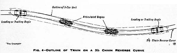
The Engineer, 1 April 1938
The above drawing shows the LMS unit on a 3½ chain reverse curve and, as can be seen, the bogie arrangement gave a shorter body pivot centres measurement than would have been the case with conventional articulation. This in turn meant that what we would today call the train's envelope was smaller and this principle equates more or less to the C1 and C3 restrictions seen on modern British rolling stock. Perhaps strangely, a few quick calculations suggest that had cars 80000/2 been reduced in length by some three feet each and car 80001, the centre car, increased in length to compensate, the same effect could have been achieved without the need for the more complex articulation and suspension arrangements. This, however, seems to have been a secondary consideration. The specific reason was said to be satisfactory operation of point locking bars but even so, it remains difficult to see why this consideration necessitated the type of articulation used. Car body weight was taken via the links to rollers on the bogie bolsters and provision was made to allow for vertical movement of the car bodies. William Stanier himself supposedly claimed this method or articulation permitted extra seating to be installed in the centre car but, like the points locking bar story, the logic behind this is rather difficult to understand.
There is another possibility which may explain the shorter length of car 80001, this being platform lengths. We have already mentioned the plan for a second unit of either two or three car configuration. It is not known which route, or routes, a production series of these diesel units was intended to operate but platform lengths at small rural stations may have dictated the length of 3-car versions, hence a shorter centre car inserted between two standard length driving cars. If this sounds strange, when the Liverpool Overhead Railway lengthened its 2-car electric units to 3-cars the centre car was shorter for precisely that reason.
The above drawing was one of several produced at Derby showing the outline of the unit of different radius curves and two, including that above, are known to have survived.
The car bodywork was of welded steel panels screwed to timber framing with internal panels of veneered plywood with mahogany framing. Veneers were West African Cherry Mahogany below the waist and Figured White Birch above in third class, with Circassian Walnut below the waist and Pacific Quilted Maple above in first class. The first class section was given decorative satin-finished cast aluminium alloy mouldings. The floors were sheet steel covered by cork, felt and linoleum. There was a thick layer of sprayed asbestos beneath the floor and above the diesel engines and asbestos was also sprayed onto the inside surfaces of the body panelling - in the body cavity, in other words.
Cars 80000/2 seated 54 third class passengers each; 26 smoking and 28 non-smoking in two areas separated by the entrance vestibule. Car 80001 seated 30 third class smoking and 24 first class passengers; the latter being divided into 16 smoking and 8 non-smoking in two separate compartments. The generous provision for smoking passengers might seem surprising to today's younger people but back in 1938 smoking was very much the fashion. It should be remembered that at the time life was full of potential health hazards; asbestos was everywhere; emission controls were unheard of and there was a chimney belching out smoke just about everywhere one looked. Pictures showing the blackened Foster's Mill at Cambridge decades ago illustrate just how dirty the air was. So smoking, those days when the health implications were by no means fully understood, was not viewed with any significance among all the other hazards of the time.
Seating in the LMS unit was of the 'throw-over' type found in tramcars. It was high backed, had padded armrests and appears from pictures to have been quite comfortable - more so than the ghastly and supposedly ergonomic seats found in modern trains, buses etc. which are made only with cheapness of production and maintenance in mind. There appears to have been adequate legroom too; something else often lacking today. Some seats were, however, fixed; those against bulkheads and a longitudinal pair in the first class smoking section of car 80001.
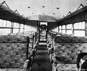 The third class area of one of the driving motor cars can be seen to the left. Behind the camera is the guard's compartment and driving cab. The partitions midway along the car are the location of the entrance doors and, on the left, a toilet compartment. Cars 80000 and 80002 were identical. Because of the toilet compartment, the number of lights (windows) at this end of 80000/2 differed from one side of the car to the other and the seats were staggered relative to each side of the car. This can be seen from the two pairs of seats in the foreground.
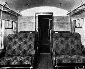 Part of the first class smoking area of car 80001can be seen to the left. Through the doorway is the small first class non-smoking area and beyond that the gangway connection into the next car. The third class area of this car also had staggered seating but the toilet compartment was on the opposite side to the previous image and a luggage rack was provided adjacent to the door opposite the toilet. Presumably the luggage rack was provided to compensate for car 80001, being the centre car, having no guard's compartment. Although somewhat spartan, the interior of the LMS unit was light and airy and in truth was probably no more uninviting than modern trains.
First class passengers had no direct access to the toilet compartment; it was necessary to leave the first class area, which was partitioned off, and access the toilet from the vestibule. Each toilet had a water tank in the roof and a basin with hot and cold running water was provided.
The matter of water heating, for the toilets, and train heating (steam at 30lb psi in a closed-circuit system) has proved problematic during research as several conflicting reports exist. A selection of these is as follows:
a) Clarkson waste heat boiler in cars 80000/2 providing steam heating and a single Westinghouse heater providing hot water for the toilets.
b) As a) but with a Clarkson boiler in all three cars.
c) Clarkson boiler in all three cars but providing hot water for toilets and with no mention of train heating.
d) As c) but with a train heating boiler in both guard's compartments.
Of those four, a) is a contemporary account from early 1938 so is probably the most reliable and is to a degree backed up by an advertisement from the 1937 British Industries Fair which has come the light and which mentions 'Two Clarkson Patent thimble Tube Silencer Boilers for new L.M.S. 3-car articulated Diesel Train'. By 1937 this boiler was quite well established and was in use on the Great Western Railway and a number of other railways around the world. The idea of utilising waste heat was a very practical and economically sensible one, but the major drawback with waste heat boilers in railway use was their inability to function unless the engines were running.
If a) is correct, the boilers in cars 80000 and 80002 must have provided heating for their own respective cars plus half of centre car 80001. This arrangement was not uncommon for electrical circuits, so its application to a steam heating circuit is not so wayward as it may appear. Another advantage with the LMS diesel unit was that only two train heating boilers were required for the whole train instead of one per car.
The Clarkson waste heat boilers were located in the toilet compartments. Each pair of engines, per car, shared a common exhaust pipe arrangement which passed, suitable enclosed, through the floor into the toilets and via the boilers before exhausting through the car roofs. The boilers also acted as exhaust silencers. But this leaves the question of centre car 80001; to confuse matters further, an unsigned and undated drawing exists showing a Clarkson boiler in 80001's toilet. If this was correct, option a) becomes somewhat discreditable.
The most likely arrangement was a Clarkson waste heat boiler in cars 80000/2 with a small Westinghouse water heater in all three toilets. This, then, would mean car 80001 must have had a conventional exhaust silencing arrangement but unless further information comes to light we will never know for certain.
.
Each car had a single leaf air-operated sliding door supplied by Messrs Peters each side. The doors could be fully controlled by the guard or set for passenger operation by means of pushbuttons located near the doors. There was a safety device which prevented the driver moving the train with any of the doors open and similarly the doors could not be opened while the train was moving. The doors to the guards compartments were of the usual double hinged type and appear to have opened outwards.
Other technical details of the LMS unit are complex and, it could be argued, beyond the scope of a feature on Cambridge station. However and as with the Michelin railcars and other unusual events, it is rather pointless telling only a small part of the story so we will continue with some of the more important technical details.
Weight of the unit in working order was a commendable 73 tons. The unit was powered by six Leyland diesel engines via Lysholm-Smith torque converters and cardan shafts to axle mounted reversing final drive units. At higher speeds, drive was direct. Freewheel devices were fitted and operated irrespective of drive being via torque converter or direct; this permitted any engine developing a fault to shut itself down while the train continued to run. Contemporary reports suggest the LMS had a very real fear of engines seizing up while in service but there is no evidence of this ever occurring. Safety devices monitoring engine oil and coolant automatically shut down any engine showing a problem. There were two sets of engine and transmission units per car, so each axle was powered apart from the outermost axle of the outermost bogies. Fuel tanks were located beneath each car but filler caps were located only on the centre car, one per side. This meant balancing pipes ran between all three cars and flexible fuel pipe connections would have been necessary between individual cars - perhaps not the best of ideas but it did simplify refuelling.
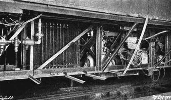
This picture and the two above and one below are from The Engineer, 1 April 1938
Above one of the engine and radiator units can be seen. The photograph was probably taken during construction. During preparation of this feature, some time was spent trying to determine precise details of these engines. Reports invariably quote nothing more than 'Leyland 125bhp at 2,200rpm'; a rather basic specification which doesn't tell us a great deal. The engines were the Leyland ERE6 with precise details being 6-cylinder vertical, 4½in bore x 5½in stroke, indirect injection, 8.6 litre overhead cam with CAV fuel injection equipment. The head was a rather odd component; 'L' shaped but mounted thus - and with fuel injectors located in the vertical component and pointing upwards at 45 degrees. This arrangement was probably adopted to facilitate maintenance with the engines in situ beneath the car floors.
This engine was specially designed for railcar use and, as we have seen, it had been used in the Northern Ireland railcars and was, it is believed, also fitted to a number of 1930s Australian railcars. Many of the latter, incidentally, continued in service into the 1980s albeit re-engined in many cases. The design of the ERE6 gave smooth and relatively quiet operation over a wide range of speeds and appears to have been entirely successful; the only problems found with the LMS unit being attributed to control servos but this was no fault of the actual engines. The initial overheating problems, already mentioned, were also no fault of the engines. What ERE6 stood for is not clear but E was a letter used by Leyland as a prefix to several engine type numbers and RE could have meant Railcar Engine. Logic says the 6 signified 6 cylinders but this does not follow Leyland's normal pattern; for example the vaguely similar engine used in the Leyland Titan TD4 bus was the E102 and this was also 6 cylinder, 8.6 litre.
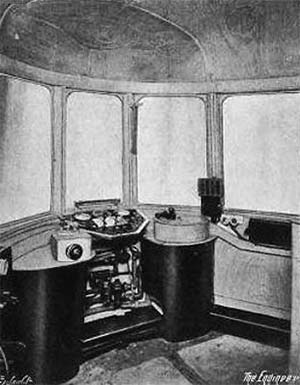 One of the driving cabs can be seen on the right, with the seat removed for clarity. Whilst the cabs were spacious and neatly laid out, the central driving position was not a very practical idea as it meant that each and every time the driver needed to exchange a token or speak to, say, a signalman or member of station staff he had to leave his seat. As we have seen, the rear window on each side of the driving cabs was a droplight but it appears the driver even had to leave his seat to open or close those as they were beyond reach from the driving position. The cabs were partitioned from the guard's compartments and accessed via a door on the left side. The photograph above was probably taken through the doorway, although there's no sign of the actual door which was hinged at its front edge and swung into the cab.
Those problems aside, the driving position was practical and comfortable. Drivers would have been pleased to find the little shelf to the left made a suitable place to stand a mug of tea. The controls for the throttle and Westinghouse air brakes were to the driver's left and right, while the 'deadman' device was a foot pedal.
A number of controls and warning lights were located on the desk in front of the driver. There was two vertical levers; one was the reverser and the other controlled the transmission. Positions of the latter were neutral, torque converter drive and direct drive. Drives were manually selected according to the train's speed and operation was electro-pneumatic. The throttle handle and reversing lever were removable and were transferred to the other end of the unit when the driver changed ends. Brakes were Westinghouse self-lapping air. The throttle control was also used for shutting down the engines, such as when the unit was being stabled. To do this, a catch had to be lifted to enable the throttle to be moved beyond the engine idle position; this caused fuel to be cut off and thus the engines shut down.
The driver's desk also contained six engine start buttons, six oil pressure warning lights (one for each engine), three engine heater plug switches and three warning lights for same (one plug switch for each pair of engines per car), compressor switch and warning light, duplex air pressure gauge for brakes, air pressure gauge for fuel pump control, warning light for sliding doors. The heater plugs preheated the engines before starting and were something of a necessity with indirect injection. Presumably as there were three switches for six engines, one switch operated the heaters of a pair of engines - thus one switch per car. The duplex air gauge is a gauge with two pointers; one indicating reservoir pressure and one indicating train pipe pressure. It is still in use today.
 The throttle controlled the fuel pumps on each engine via pneumatic servos and was self-lapping, meaning that speed could be held according to the throttle lever position. This system was a source of trouble on the LMS unit and was overcome simply by driving the train at full throttle and then either letting the engine speed governors take control or, once the required speed had been reached, throttling back and letting the engines freewheel. The unit could not be moved unless air pressure was 60psi or above, nor could it be moved with the sliding doors open as already mentioned.
The drivers desk was illuminated by a strip light mounted at the bottom of the central windscreen. The box mounted on the pillar to the driver's right was the Loudaphone device for communicating with the guard. Next to the Loudaphone was two switches marked, apparently crudely by hand, F and R. Presumably this signified Front and Rear and were references to the unit's two guard's compartments.
Other controls in the cabs were for the windscreen wiper, cab light, whistle and the single electric headlight. Presumably the cabs were heated by the same supply which served the passenger sections.
As we have seen, the unit entered Wolverton Works on 29 June 1938 for modifications. On 12 September of that year it reappeared on the Oxford - Bletchley - Cambridge route in its new red+cream+silver livery, minus valances (evidence suggests these had been removed previously) and with a few other modifications including to its springing. Apparently during the period of testing the ride had been quite lively, although it is not known if any weight was added to simulate passenger loading. Based at Bletchley, the unit this time entered passenger service. The services it operated were in addition to the normal timetabled services and were advertised by handbill. The handbill gave no guarantee the services would run but, to the credit of the LMS, a steam train was held in standby - just in case. Although the steam train was for passengers convenience should the diesel fail, the LMS was probably more mindful of the adverse publicity which may have resulted if the diesel failed and passengers were left stranded somewhere for hours. After all, the regular service on the Oxford - Cambridge route was hardly frequent. How the steam train operated is not known; it may have lurked somewhere along the line or it may have shadowed the diesel along part of the route. In all probability it was a Push-Pull train as this would have provided the most flexibility at short notice.
Passenger services operated were as follows:
- 8.48am Bletchley - Cambridge
- 10.42am Cambridge - Oxford
- 1.42pm SX Oxford - Cambridge
- 1.47pm SO Oxford - Cambridge
- 4.15pm Cambridge - Oxford
- 6.25pm Oxford - Cambridge
- 8.40pm Cambridge - Oxford
- 10.45pm SX Oxford - Bletchley
- 11.10pm SO Oxford - Bletchley
This gave a service mileage of 462 per day. The diesel did not operate on Sundays. The handbill informed intending passengers that Existing cheap facilities are available on these services. In plain English this meant the the fares were the same as the normal steam services. Calling points were Oxford, Bletchley, Bedford St Johns, Sandy and Cambridge. In addition, the 10.45pm SX also called at Bicester and Winslow while the 11.10pm SO called at Islip, Bicester and Winslow.
The unit operated the above services from 12 September 1938 to 2 January 1939. During this time it managed a period of 49 consecutive days, Sundays excepted, without any problems at all and amassed a total of 22,638 miles over those 49 days. Whilst this might seem good, by railway standards it was poor and over the entire 12 September 1938 to 2 January 1939 period its availability was only around 50%.
The withdrawal date of the unit's Oxford - Cambridge spell was preplanned and not the result of any failure. It was next allocated to Bedford and from March 20th 1939 it began operations, in service, between St Pancras, Leicester and Nottingham. This time, some of the services it operated replaced existing steam services. The diagram was:
- 5.50am Bedford - St Pancras
- 11.10am SO St Pancras - Leicester
- 11.20am SX St Pancras - Leicester
- 2.45pm Leicester - Nottingham
- 5.25pm Nottingham - St Pancras via Melton Mowbr
- 10.35pm St Pancras - Bedford
Of these, the 5.50am was formerly a steam service which only ran as far south as Luton, while the 10.35pm had a lengthy stop at Luton from where it departed at 11.45pm. This latter was an additional service; the 10.35pm as far as Luton having formerly been a steam service.
Unit 80000-2 appears to have been rather more reliable on these services than it was on the Oxford - Cambridge services. It was during its spell on the Midland main line that it gained wire mesh over the windscreens. This was said to be to prevent damage from flying stones but from whence the stones flew was not stated; it might have been from passing trains of open coal or mineral wagons or it might have been due to vandalism - certain routes of the former Midland Railway were especially prone to this at one time. In any event, it appears the mesh was removed again at some point during the unit's spell working from Bedford.
The unit was placed into store upon the outbreak of the Second World War and finally withdrawn from service in February 1945. Where it was stored during the war is unclear; some reports say Chaddesden Yard while others say Bedford. Anecdotal evidence, however, suggests Chaddesden. Other reports state it was returned to Bedford after the war while another reports it as being seen at Spondon in April 1946.
Its ultimate fate was conversion into an overhead maintenance unit for the Manchester South Junction & Altrincham line, then a 1500v DC route. The conversion altered the unit almost beyond recognition; the centre car was removed, the streamlined cabs were rebuilt with flat ends, proper buffing and drawgear was fitted, the roof was flattened and made into a walkway and only two engines were retained. Renumbered M198895/6M it towed a wire wagon built on the underframe of a redundant carriage. It was apparently based at Stretford. It seems M198895/6M saw little use and was noted stored, in scruffy condition, at a number of locations at different times although it had later been given new torque converters and a coat of malachite green at, it is believed, Horwich.
By 1959 it was at Longsight, apparently out of use and derelict, and remained there until the end of 1967 when it was scrapped, presumably on site. The centre car was almost certainly dismantled for spares and the remains scrapped at the time it was removed from the unit.
As a passenger train, 80000-2 had its problems and had failed on a number of occasions but most problems were minor and could have been - indeed were in many cases - overcome. Some of the problems were simple things like wiring errors, leaking pipes, flat batteries and so on. It is a great shame the project ground to a halt but war brought more important concerns for the LMS and Leyland had stopped its railway activities to make way for war production. Post war, the general state of the railways took priority and following nationalisation BR looked towards electrification and building its own design of diesel multiple units - the Derby Lightweights.
It seems a little odd that while the 3-car diesel unit was stored during the war, the three Leyland railbuses 29950-2 continued in service. The answer to this probably lies in the fact the LMS did not, apparently, consider these railbuses to be experimental. Nos.29950 - 2 operated in Lancashire but later ended up in Scotland, where they survived into BR ownership. They were finally withdrawn in April 1951 after a life of 18 years; rather better than the BR railbuses of the 1950s which struggled to see ten years.
One puzzle remains concerning the LMS diesel unit, this being precisely what the LMS intended for it. It was capable of operating long distance services but passengers on such services would have expected buffet or restaurant facilities. The unit would have been hopeless on busy suburban services due to having only one single leaf door per car per side. It would have been an overkill to operate it on rural branch lines so that leaves secondary routes such as Oxford - Cambridge. Perhaps semi fast services on this route and others like it was the intention; certainly the LMS made a big thing out of the reduction in journey time compared to steam trains on the Oxford - Cambridge route (this was actually somewhat misleading because the majority of steam trains made more intermediate stops). But the unit's transfer to the Midland main line suggests routes like Oxford - Cambridge were not the intention after all. We will never know.
The Conductor-Guard Trains
These 3-car sets were, insofar as Cambridge was concerned, peculiar to the Mildenhall Branch but other types operated on various branches in East Anglia at different times during the steam era; Wisbech & Upwell Tramway; Elsenham - Thaxted; Kelvedon - Tollesbury to name three. The subject is covered in the Mildenhall branch section of Disused Stations but due to image availability some coverage is appropriate here.
© John Alsop Collection
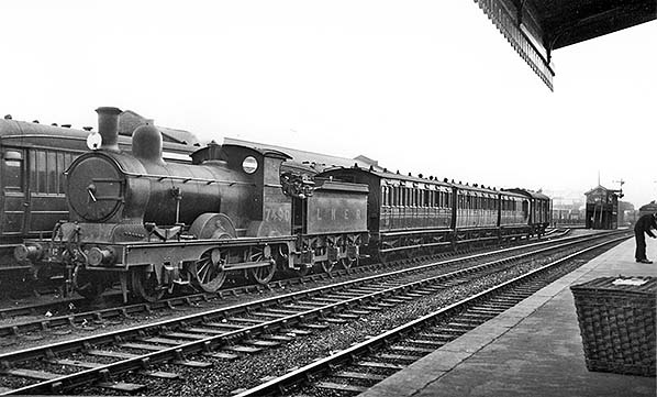
The Mildenhall branch train above is in LNER livery and the 1926 signalling is in place. The 6-wheel conductor-guard stock had all been withdrawn by 1940 so the date is somewhere between 1926 and 1940. The clerestory coach on the left appears to be an ex GER semi-corridor lavatory composite. It must be market day as the train has been strengthened to five vehicles by the addition of an extra third and an extra brake.
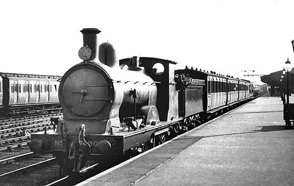
© John Alsop Collection
Above another Mildenhall branch conductor-guard set can be seen in the carriage sidings opposite platform 1 of Cambridge station. This is a standard 3-car set but with a Diagram 87 milk van coupled on the rear. These vans were built for use on ex-Great Eastern lines and were used for the conveyance of all manner or perishable goods including milk. In Part 1 we mentioned how trains became larger as the years progressed and the size of the milk van compared to the train it is coupled to illustrates this very well. Even the locomotive is somewhat dwarfed by the Gresley vehicle beside it.
Close examination of the train will reveal the gangway connection behind the locomotive tender and the sealed-up doorways of the carriages. The retractable steps for use at the halts on the Mildenhall branch were fitted to the brake vehicle and were on the opposite side to that seen in this view. The three halts were all on the up side of the Mildenhall branch so steps were only needed on one side of the trains. If for any reason the carriages ended up the wrong way round, they could either be turned individually on a locomotive turntable or a complete set could be turned on the Newmarket triangle.
The conductor-guard sets were converted for the opening of the halts in 1922. Considering the infrequency of the Mildenhall services, a surprisingly large number were converted - some 40 individual carriages in total. However, not all existed at any given time; some were withdrawn and replaced by other conversions while a number of others were held spare for strengthening purposes, as evident in the previous image. All the 6-wheelers had gone by 1940, replaced by converted bogie stock.
In both images the locomotive is E4 No.7490. This was to become the famous BR No.62785; the final 2-4-0 locomotive in service with British Railways and now preserved.
 Home Page